
Estimated Study Time: 18 minutes
Primary Distribution Systems
The primary distribution system of an industrial plant is generally the higher voltage portion of the system, starting with the purchased-power service and including generators, switching equipment, circuits, and all transformers with secondary voltages higher than 600 V. This technical article tends to explain the main substations and typical bus arrangements in the primary distribution system of an industrial plant.
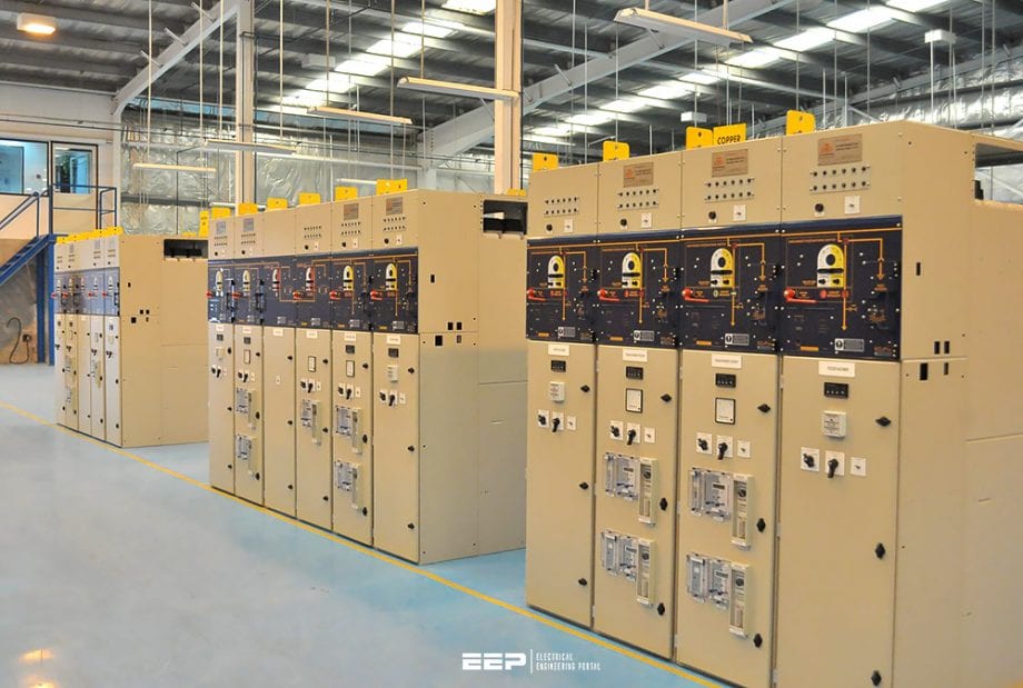 Primary substations and bus layouts in the distribution system of an industrial plant (photo credit: HS Switchgear FZCO)
But, first, let’s say a word about planning such complex distribution system for an industrial plant. Coordinated planning guided by overall system characteristics is the only way desired design objectives can be achieved. Such system characteristics as cost, safety, reliability, flexibility, and simplicity should be viewed together only, because they will be interrelated in varying ways.
Distribution system arrangements tending to favor a particular desirable characteristic will most often tend to produce compromises in one or more other desirable characteristics.
The general idea is to provide more than one power channel around system components that need maintenance or might fail. Increased investment for such provisions may be money wasted unless the system is well planned in some other respects.
The primary requirements for good service reliability are that good-quality adequate equipment will be selected, that it will be properly installed, and that it will be well maintained.
Main substations
Not all plants own and operate a main substation for supplying the primary distribution system. A plant main bus serves the same purpose if the purchased-power voltage is suitable without transformation for the plant primary system.
The principal functions of a main substation are indicated in Figure 1, which is a simple arrangement answering the requirements of a great many smaller plants.
More complicated substation arrangements result when there are two or more incoming lines, two or more power transformers, or one of a number of other bus arrangements: Also in plants with power generation, the substation output may not supply a plant main bus but may be connected to a synchronizing bus.
Figure 2 differs from Figure 1 in using power fuses instead of a circuit breaker in the incoming line. Circuit breakers are generally preferable, but fuses will be useful in satisfying over-all objectives in some of the smaller and simpler substations.
When substation primary fuses are used, it is better to employ solid neutral grounding of the transformer secondary than to limit the ground-fault current in the primary distribution system.
Stated in another way, a given high-voltage breaker arrangement for a given supply system will cost just about the same regardless of the substation size. The discussion is intended simply to indicate what the several arrangements offer.
Figure 3 shows a two-line single-transformer substation using two high-voltage circuit breakers. This arrangement might be used whether the two lines are alternate, paralleled, or part of a loop.
For a loop supply, the substitution of a circuit breaker for the transformer horn-gap switch would avoid opening the loop by the transformer protection scheme. The use of either two or three circuit breakers might be hard to justify in particular cases.
For alternate-line or preferred-emergency supply, the single circuit breaker in Figure 4 with interlocked incoming line switches has a minor deficiency in not permitting an automatic transfer between lines.
Either Figure 3 or Figure 4 permits expansion by adding one or more transformers to the high-voltage bus. Figure 5 is simply an extension of Figure 3 for a two-transformer substation where the two incoming lines are alternate, paralleled, or part of a loop.
As illustrated with four high-voltage breakers, this substation arrangement can provide an unusually high degree of service reliability, except for a high-voltage bus fault.
For the special case of two incoming lines that may be operated in parallel but are not a loop supply, the arrangement of Figure 6 is often a good solution.
However, the station-cost reduction may be so significant for smaller substations that load curtailment during an outage becomes an acceptable risk.
It is moreover possible to reinvest part of the circuit breaker saving in additional size of transformer units to achieve service continuity for all the load or to reduce the amount of load curtailment during half-capacity operation.
Referring again to Figure 6 in connection with loop supplies only, the high-voltage part of the substation employs almost all the circuit breakers that can be fitted into a single-bus arrangement.
However, a fifth circuit breaker could be added in the bus. With appropriate relaying, it would ensure continuity of service through one transformer under the condition of a high-voltage bus fault.
It is perhaps more profitable to observe how reliability and flexibility are modified by removing circuit breakers one at a time, as illustrated in Figure 7 to Figure 10. In the three-breaker scheme of Figure 7 the main functional compromise is that transformer protection requires opening the loop supply.
A utility would not ordinarily consider this as a serious shortcoming, but it could be avoided in the alternative three-breaker scheme of Figure 8. Either of these arrangements provides service continuity through one transformer for any single fault, including a high-voltage bus fault.
In the two-breaker scheme of Figure 9, operation of the protective relaying of either transformer not only opens the loop but drops the whole substation load. The loop can be reclosed and plant service can be reestablished through the unfaulted transformer circuit by manual switching.
A permanent high-voltage bus fault must, of course, be repaired before either circuit breaker can be reclosed.
In attempting to use a single breaker as shown in Figure 10, a problem is encountered. Any high-voltage fault down to the transformers will be cleared by the single circuit breaker and the utility as a single-line short circuit, leaving uninterrupted plant service through one transformer.
However, there will be a level of transformer fault current below which the utility cannot trip, and the faulty unit cannot be automatically disconnected from the system at such a level of overcurrent except by transferred tripping of a power-company circuit breaker using carrier or a pilot wire.
Bus arrangements
A bus is a junction of three or more incoming and outgoing circuits. The most common plant bus arrangement consists of one source or supply circuit and two or more feeder circuits. The numerous other arrangements and variations are mainly intended to improve the service reliability through the bus to all or part of the load during expected maintenance, or in the event of equipment failure or source outage.
These same bus arrangements will seldom prove acceptable for cost reasons in medium-size and small systems even when service continuity is considered to be unusually important.
The highest quality of service reliability can often be obtained more economically for smaller plants, particularly for those with load-center systems, by over-all system arrangements that employ simpler and less costly bus arrangements.
The double-bus arrangement shown in Figure 11 is an example of the more complicated arrangements that is technically sound if good-quality equipment is used, but it is very costly for the usual sizes of feeder circuits.
The arrangement is suitable for outdoor circuit breakers, station-type cubicles, or metal-clad construction. In metal-clad switchgear, some requirements can be met a t lower cost by employing two positions and one circuit breaker per circuit plus one spare removable circuit-breaker element, as illustrated for one of the several circuits.
This variation still allows transferring any circuit or maintaining any circuit breaker without a feeder interruption.
Figure 11 was intended to indicate a preferred physical arrangement with companion circuit-breaker compartments in separate standard equipment facing each other across an operating aisle. A cable connection would usually join the circuit breakers.
Figure 12 illustrates a typical two-source sectionalized-bus arrangement with a single circuit breaker per line. Figure 12 or some variation places lines and breakers on the same basis of availability.
Where metal-clad switchgear is used in the primary system, a feeder outage for circuit-breaker maintenance can be reduced to a matter of minutes with a spare removable circuit breaker on hand.
In extending reliability from a main bus to a sub-bus in an important load area, parallel feeders may be used. In the load-center system each load-center transformer has the same availability as its primary feeder and supply breaker. Improvement in service reliability is secured by interconnection at secondary voltage.
When three or more sources are available at a main bus, Figure 13 is a natural extension of Figure 12.
However, Figure 14 is more flexible and is usually preferred even when another circuit breaker is needed. This arrangement may be referred to as a star bus, but it also is sometimes called a synchronizing bus arrangement whether any of the sources is a generator or not.
Particularly if reactors are needed to parallel the sources, Figure 14 will be preferable to a straight bus (or a riug bus) with the current-limiting reactors installed between each tie circuit breaker and the common bus.
The need for tie circuit breakers is obvious in some straight buses, but there are other cases where the value may be in doubt.
Experience shows they are too often omitted where a choire rail can be made in the planning stage. The following remarks are intended to summarize the various ways in which bus-tie circuit breakers may be useful initially and later.
When two sources are used simultaneously but must not be operated in parallel, a normally open bus-tie circuit breaker interlocked with the source circuit breakers permits serving both bus sections from one of the sources when the other is not available.
For alternate (or preferred-emergency) or normally paralleled sources, a single straight bus may be used. It is preferable to use a normally closed bus-tie circuit breaker so that one bus section can be kept available when the other is out for maintenance or repair or to permit additions during a plant expansion.
For paralleled sources, relaying of the tie circuit breaker may be employed to split the system so that service continuity is retained on one bus if the other bus fails or it became necessary to back up a feeder circuit breaker on that bus.
Sources: Industrial Power Systems Handbook by Donald Beeman
Related electrical guides & articles


Edvard Csanyi
Hi, I'm an electrical engineer, programmer and founder of EEP - Electrical Engineering Portal. I worked twelve years at Schneider Electric in the position of technical support for low- and medium-voltage projects and the design of busbar trunking systems.I'm highly specialized in the design of LV/MV switchgear and low-voltage, high-power busbar trunking (<6300A) in substations, commercial buildings and industry facilities. I'm also a professional in AutoCAD programming.
Profile: Edvard Csanyi

Pre-commissioning test on transformer and expected values from the test analysis.