
Estimated Study Time: 5 minutes
Differential protection
Although nowadays differential protection is achieved numerically, in order to understand the principles of differential protection it is useful to analyze the ubiquitous electromechanical relay. Figure 1 shows a simple differential protection scheme, also known as a Merz-Price scheme.
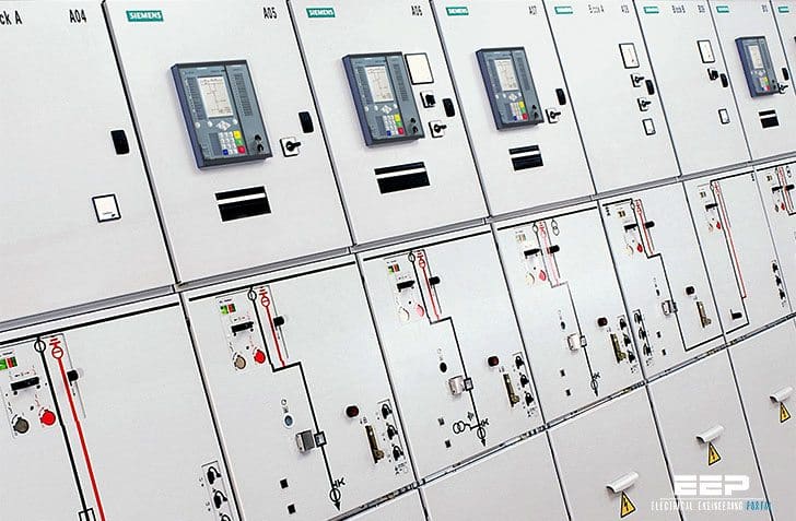 The principles of differential protection you MUST understand (on photo: SIPROTEC protection relays)
In this simple scheme, we can assume that under normal operating conditions, the current entering into the piece of equipment under protection is equal (or in the case of a transformer, proportional) to its exiting current. In this example, we will assume that the entry and exit currents are equal.
A circuit breaker on either side of the equipment under protection is controlled by an overcurrent relay.

Current transformers of identical types and turns ratio are installed on either side of the equipment. These current transformers induce identical secondary currents because their primary currents are identical and they have the same turns ratio.
By simple inspection of the diagram, it is clear to see that under these circumstances no spill current will flow through the relay, therefore no trip signals will be generated.
…and when the fault occurs
Consider a fault internal to the equipment. A large current would flow through the fault, thus the current exiting the equipment would rapidly reduce resulting in a reduced secondary current in CT B. This would cause a current to flow through the relay, which would be of a magnitude sufficient to trip the circuit breakers.
Now consider an external fault at F as shown in Figure 2.
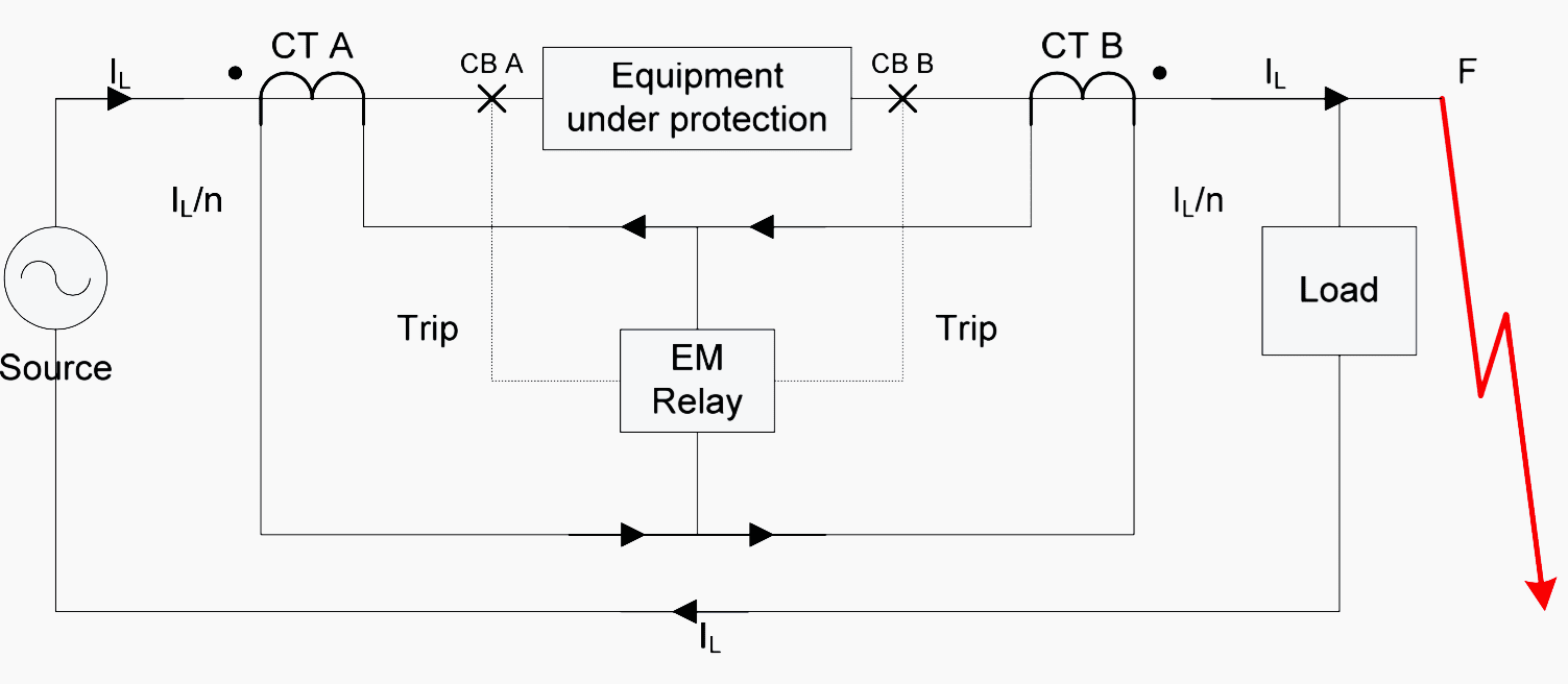
You can see that in this case, the current exiting the equipment, albeit large, is still the same as the current entering it, therefore the relay will not trip. This is exactly as how we want it, because faults external to the equipment are in a different protection zone and are protected within another scheme.
If the equipment to be protected is a busbar, or generator winding, for instance, it is clear that the exit current is the same as the entry current. If, however, the equipment is a transformer where the turns ratio is not equal to one, the current entering will be different from the current exiting.
In this case, the current transformers must be balanced with an equivalent turns ratio differential.
A differential scheme should therefore be able to respond to the smallest of internal faults, but restrain on the largest of external faults.
In practice, this is difficult to achieve – especially for very large through faults, due to the non-ideal nature of the current transformers used to measure the currents. The term used to specify the system’s ability to cope with these imperfections is called Through-fault Stability.
In modern IEDs (Intelligent Electronic Devices), the current in the current transformers do not directly control the operating coil which trips the circuit breakers, so the connectivity is not as it is shown in this example. In reality, the currents from the current transformers are simply input to the IED, where they are sampled and digitized.
The differential operation is then carried out by the IED’s software.
Basic Transformer Differential Theory (VIDEO)
Reference // Substation Automation Principles by Michael J. Bergstrom
Related electrical guides & articles


Edvard Csanyi
Hi, I'm an electrical engineer, programmer and founder of EEP - Electrical Engineering Portal. I worked twelve years at Schneider Electric in the position of technical support for low- and medium-voltage projects and the design of busbar trunking systems.I'm highly specialized in the design of LV/MV switchgear and low-voltage, high-power busbar trunking (<6300A) in substations, commercial buildings and industry facilities. I'm also a professional in AutoCAD programming.
Profile: Edvard Csanyi

The fault that you give is outside the zone of differential relay!
in this case there will be no spill current hence no triping will occur.
tripping will only occur if the fault is inside the zone then there will be difference between two current!
33/0.4kV, 4000kVA. how to calculate knee point voltage and exciting current.
Dear Sir,
We Have Transformer plus Cable differential protection achieved through 7SD610 Numerical Relay.
Recently We have observed that R phase outzone fault in other feeder cause activation of B phase differential protection without any fault. can u tell why?
Very detailed but simple to understand piece.I am preparing to be tested for 33KV switching and the simple explanations in this article have made it very interesting for me to read
Earlier I had asked few questions to Edward, but till date I didn’t get any reply from him. Is there any unwritten protocol that no replies shall be given, is that so??
Could you, please, clarify how does thr alghorithim of the digital relay computes reading the fault?
With the static and electromechanic relays the basis was angle measurement. Static used the coincidence+ anti-coincidence principle of the formulae and integrated them so that by triggering the integrated value you would be able to tripp the switching device.
/as far as I know, digital devices use the DFT Discrete Fourier Transformation but I would be pleased if you could develop it so that it can be more ´´digestible´´.
I thank you in advance.
Kind regards
emmanuel