
Estimated Study Time: 21 minutes
Programming of microprocessor relays
Developing basic setting specifications for numerical relays is a boring process for most electrical engineers, but not for the protection engineers! It requires significant input data but, for the most part, is exciting and relatively straightforward.
 6 tools you MUST learn before programming numerical protection relays for real (photo credit: Lucy Electric)
A basic understanding of Boolean expressions and methodologies is helpful in developing the required programing to obtain the desired logic and for effectively using the full power that is designed into numerical relays.
The capabilities and power that are built into microprocessor relay designs are continually expanding. In addition to providing an array of protective functions, capability to fulfill most of the control and data acquisition requirements at substations is provided.
Many modern numerical relays possess the power to replace other digital devices that are required within substation control and data acquisition systems such as PLCs, RTUs, meters, and control switches.
Protection engineers are not necessarily proficient in programing techniques and, as such, they may be hesitant to apply numerical relays such that their full capability is used.
Programming tools
An understanding of programing techniques is required to effectively use the many features and flexibility that are designed into modern microprocessor-based relays.
Programing tools available for programing modern numerical relays include:
- Boolean Algebra
- Control Equation Elements
- Binary Elements
- Analog Quantities
- Math operators
- Relay settings
Also, let’s mention the enhancements achieved by numerical relays in distribution and transmission system with mentioning of some most typical examples:
1. Boolean Algebra
Knowledge of Boolean algebra and its relationship to logic created by electrical circuits is important to facilitate the task of programing numerical relays.
Many good texts and courses are available for obtaining knowledge of this subject area. A brief overview of some basic fundamentals follows.
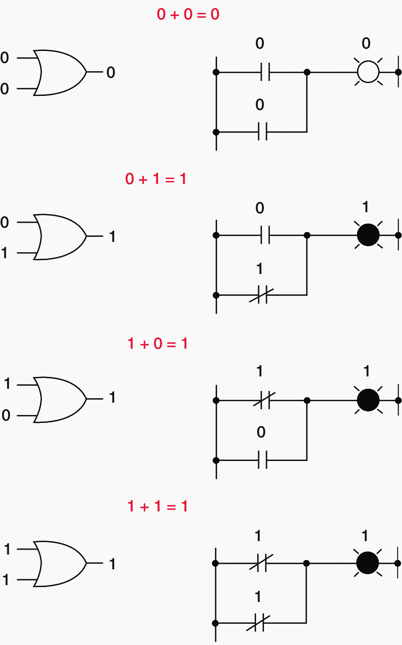
In Boolean arithmetic, terms can only have two states—they can be either a 1 or a 0. Rules for Boolean addition are illustrated in the following equations:
0 + 0 = 0, 0 + 1 = 1,
1 + 0 = 1, 1 + 1 = 1
It does not matter how many terms are added, the sum cannot be any larger than 1 since, as noted earlier, only 1 and 0 can exist:
0 + 1 + 1 = 1,
1 + 1 + 1 + 0 = 1,
1 + 1 + 0 + 1 + 1 + 0 = 1
Boolean addition corresponds to the logical function of an ‘‘OR’’ gate and is representative of parallel contacts in an electric circuit. The basic equations for Boolean addition along with its logical ‘‘OR’’ gate and electric circuit representation are illustrated in Figure 1 above.
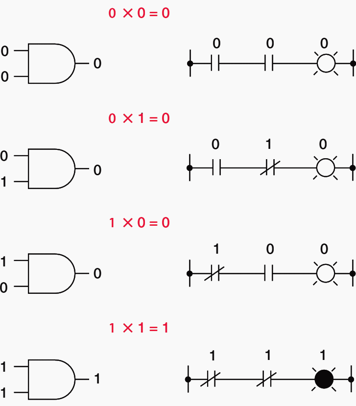
Following are the equations that represent the rules for Boolean multiplication:
0 × 0 = 0,
0 × 1 = 0,
1 × 0 = 0,
1 × 1 = 1
Boolean multiplication corresponds to the logical function of an ‘‘AND’’ gate and is representative of series contacts in an electric circuit.

Figure 2 illustrates expressions for Boolean multiplication. Boolean algebraic variables are denoted by capital letters.
A complement is referred to as a logical inversion and corresponds to the logical function of a ‘‘NOT’’ gate.
Electrically, a logical inversion is equivalent to a normally closed contact. Expressions for Boolean complementation are illustrated in Figure 3.
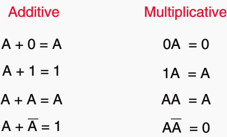
As in mathematics, identities also exist in Boolean algebra. These identities are derived from the unique bi-variable nature of Boolean variables.
Basic Boolean additive and multiplicative identities are illustrated in Figure 4 below.
Boolean algebra also contains cumulative and associative properties.
- Cumulative property of addition: A + B = B + A
- Cumulative property of multiplication: AB = BA
- Associative property of addition: A + (B + C) = (A + B) + C
- Associative property of multiplication: A(BC) = (AB)C
- Distributive property: A(B + C) = AB + AC
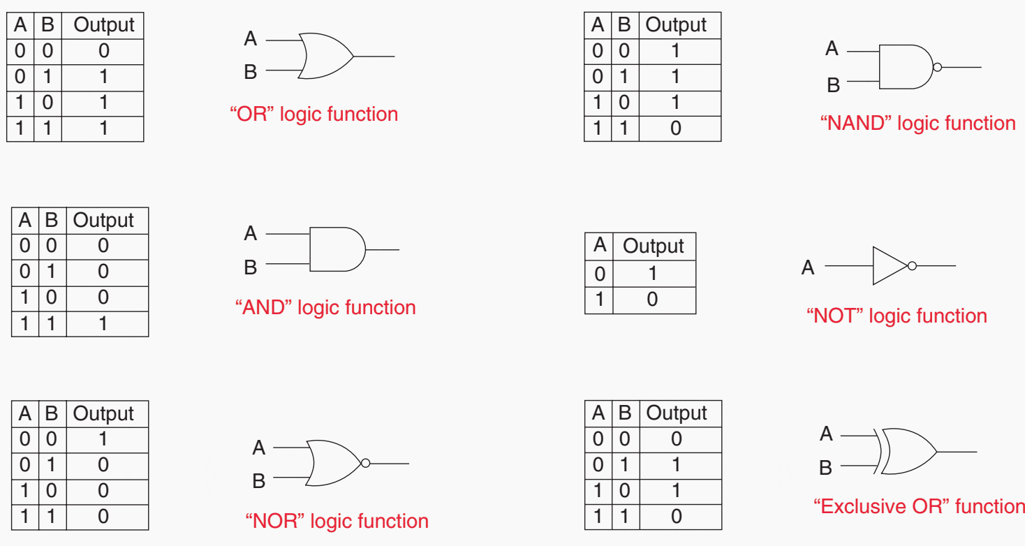
Some other operators used in Boolean expressions include comparisons (<, >, = , etc.), parentheses, and rising and falling edge triggers. Numerical relays often use symbols to represent Boolean operators (i.e., + = OR,* = AND, ! = NOT).
To promote programing efficiency, the initial expressions developed from the truth table should be reduced, using the laws of Boolean algebra, to a simplified form. The required logic circuit can then be developed from the simplified expression.
Figure 5 illustrates truth tables for a variety of logic gates used in logic diagrams.
Example
The following example illustrates the process of developing logic for control circuits:
Three pilot relaying systems are applied on a very important transmission line. In order to enhance security of the line it is desired that trip outputs from two out of the three pilot systems must be present for a trip of the line to be initiated.
Related electrical guides & articles


Edvard Csanyi
Hi, I'm an electrical engineer, programmer and founder of EEP - Electrical Engineering Portal. I worked twelve years at Schneider Electric in the position of technical support for low- and medium-voltage projects and the design of busbar trunking systems.I'm highly specialized in the design of LV/MV switchgear and low-voltage, high-power busbar trunking (<6300A) in substations, commercial buildings and industry facilities. I'm also a professional in AutoCAD programming.
Profile: Edvard Csanyi
