
Estimated Study Time: 35 minutes
Maintaining CT installations
Welcome to the third and final part of our comprehensive series on current transformers (CTs) and their secondary circuits. In Parts 1 and 2, we covered various aspects of CT operation, secondary injection testing, burden calculations, CT circuit connections, safety measures, and testing procedures.
 Hints and warnings for proper installing, earthing and testing of current transformers
If you haven’t had a chance to read Part 1 and Part 2, we highly recommend doing so to gain a complete understanding of CT fundamentals and reliable operation.
In Part 3, we will focus on ensuring proper installing, earthing, and testing of current transformers. These aspects are crucial for maintaining the accuracy, reliability, and safety of CT installations. CT ratio selection is an essential step in CT installation and handling unused CT taps properly is equally important.
We will discuss the factors to consider when selecting CT ratios and provide guidance on handling unused CT taps to ensure optimal CT performance and avoid any potential issues.
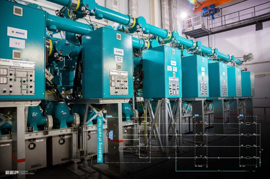
Proper earthing of CT secondary wiring is vital for system safety and reliable operation. We will emphasize the importance of earthing the CT secondary wiring at a single point only and explore different case studies that highlight the consequences of multiple earth points. Understanding the impact of earth fault currents and potential bypassing scenarios is crucial for designing effective earthing systems.
Determining the earthing requirement for electrically connected CT secondary windings is another topic we will address. We will discuss the considerations for choosing between a single earth point and multiple earth points and their implications on system performance and safety.
Proper grounding in CT circuits is essential for reliable measurements and system protection. We will refer to the IEEE Standard C57.13.2 to outline the guidelines for adhering to proper grounding practices. Understanding and implementing these standards will help maintain the integrity of CT circuits and ensure accurate measurements.
Performing a single earthing test during CT loop commissioning is an essential step in verifying the effectiveness of the earthing system. We will provide a step-by-step guide to conducting this test and interpreting the results to ensure the safety and reliability of the CT installation.
Ensuring accurate phase identification of CT wiring is essential for proper system operation. We will explain the importance of performing phase identification tests and guide you through the process to verify the correct wiring configuration.
Verification of CT wire size during CT secondary loop testing is critical for accurate measurements and system integrity. We will discuss the significance of verifying the CT wire size and provide guidelines on how to ensure it meets the required specifications.
Accurate identification of CT secondary wiring is essential for maintenance and troubleshooting activities. We will emphasize the importance of verifying CT secondary wiring ferrules or labels to ensure accurate identification, making it easier to identify and rectify any issues that may arise.
Verification of CT secondary cable insulation is necessary to maintain the integrity and safety of the CT system. We will discuss the importance of inspecting the cable insulation and provide guidelines on how to perform this verification effectively.
Secure crimping of lug connections is crucial for maintaining proper electrical connections in the CT circuit. We will explain the concept of crimping and highlight the significance of inspecting lug connections for secure crimping to avoid any potential issues.
In this final part, we aim to provide you with the knowledge and guidance necessary to ensure the proper handling, earthing, and testing of current transformers. By following the recommendations and procedures outlined in this series, you can enhance the reliability, accuracy, and safety of CT installations.
- Understanding Multi-Ratio Current Transformers and Managing Unused CT Taps
- Managing Unused CT Cores: Best Practices and Recommendations
- The Significance of Proper Grounding: Ensuring Single-Point Earth Connection for CT Secondary Wiring
- CT Earthing Requirement for Electrically Connected CT Secondary Windings: Choosing Between a Single-Earth Point or Multiple Earth Points?
- Importance of Proper Grounding in CT Circuits: Adhering to IEEE Standard C57.13.2
- Performing the Single Earthing Test during CT Loop Commissioning
- How to Perform Insulation Resistance Test of CT Wiring
- How to Perform Current Transformer Wiring Phase Identification Test
- Importance of Wire Diameter in CT Circuits: Sizing and Selection Guidelines
- Verify CT Secondary Wiring Ferrules / Labels for Accurate Identification
- Verification of CT Secondary Cable Insulation
- Inspect Lug Connections for Secure Crimping
- BONUS! IEEE C57.13 Standard Requirements for Instrument Transformers (PDF)
1. Understanding Multi-Ratio CTs and Managing Unused CT Taps
A multi-ratio current transformer offers the flexibility to choose different ratios by selecting the desired tap either at the secondary side or the primary side of the CT These CTs are equipped with various winding taps, enabling users to choose their desired ratio from the available options.
Typically, these CT models provide up to ten different ratios, and they are commonly utilized in relaying applications.
To determine the correct tap for your application from the provided diagram on the nameplate of a multi-ratio current transformer, follow these steps:
Step #1 – Identify the available winding taps: Examine the diagram on the nameplate, which illustrates the different winding taps on the CT. These taps represent the various transformation ratios that can be selected.
Step #2 – Determine the required transformation ratio: Evaluate the specific requirements of your application and determine the appropriate transformation ratio needed. This ratio is typically based on the current levels expected in the system and the sensitivity of the protective relaying equipment.
Step #3 – Locate the corresponding tap: Once you know the desired transformation ratio, locate the tap on the diagram that corresponds to that ratio. The diagram should provide clear markings or labels to identify each tap.
Figure 1 – Example of multi-tap current transformer
The diagram shown in Figure 1 , depicts the available tap connections denoted as X1, X2, X3, X4, and X5, which are accessible to the user. When the current transformer (CT) is connected across taps X1-X5, it achieves its full rating of 600:5. However, if the user requires a different current rating, they need to select an alternative tap.
These numbers represent the number of turns between the different taps. For instance, there are 20 turns between X1 and X2, 10 turns between X2 and X3, and 80 turns between X1 and X4, among other combinations. These turn values indicate the winding ratios between the respective taps and provide a means for selecting the desired current transformation ratio.
Let’s consider an example to illustrate the process. Suppose we want to use the aforementioned 600:5 current transformer (CT) for a 150:5 application. In order to select the desired ratio we need to follow following steps:
Step #1 – Divide the desired current ratio of 150:5 by the CT’s full rating ratio of 600:5. This calculation results in 30.
Step #2 – Referencing the figure provided earlier, examine the tap combinations to identify the one that yields a total of 30 turns. In this case, the combination that satisfies this requirement is X1-X3.
Step #3 – Connect the CT’s secondary leads between taps X1 and X3, and leave the other taps open. This configuration allows us to obtain a 150:5 CT.
By selecting the appropriate tap combination, in this case, X1-X3, and connecting the CT accordingly, we effectively modify the current transformation ratio to suit our desired application.
Figure 2 – CT ratio and taps positions

There are two methods commonly used to present the information on a current transformer (CT) name plate. The first method involves indicating the number of turns and referencing a corresponding Figure 2 for further details. The second method involves directly stating the ratio on the name plate. When the ratio is provided on the name plate, it becomes more convenient to select the desired ratio without the need for additional references.
Please refer to Figure 3, which illustrates a name plate of a CT displaying terminal numbers and the corresponding CT ratios.
Related electrical guides & articles


Muhammad Kashif
Muhammad Kashif Shamshad is an Electrical Engineer and has more than 17 years of experience in operation & maintenance, erection, testing project management, consultancy, supervision, and commissioning of Power Plant, GIS, and AIS high voltage substations ranging up to 500 kV HVAC & ±660kV HVDC more than ten years experience is with Siemens Saudi Arabia.Profile: Muhammad Kashif
