
Estimated Study Time: 22 minutes
Be Careful With a Phase Sequence
Phase sequence or phase rotation is one of the most confusing concepts in the electrical engineering. It is often confused with motor rotation. For instance, one would say: “If it doesn’t turn the way you want it, just rewire two phases and the motor will turn correctly.” That applies well for most of the motors, but not for the large generators.
 The issue of a proper phase sequence (CW or CCW) on electric motors and generators
The issue of a proper phase sequence, clockwise (CW) or counterclockwise (CCW), has a different impact on the electrical equipment, such as:
(1) Phase sequence of the source equipment (generation).
(2) Phase sequence of utilization equipment (motors).
- Motors
- Generation
- Phase Sequence Convention CCW and CW
- Phase Sequence Mistakes
- Conclusions
- BONUS (PDF) 🔗 Download ‘Implementation of Loss-of-Synchronism Protection Systems for Generators’
1. Motors
Typically, the pumps and fans are designed for a specific direction of rotation. The mechanical rotation is usually marked on the driven equipment. Before starting the pump, the pump is uncoupled from the motor and the motor direction of rotation is checked. If the rotation does not match that of the related fan or pump, the phase sequence is changed by reversing two phases.
This can be done at the motor terminal box or at the source; or preferably at MCC or switchgear. One does not even pay attention if the required phase sequence is CW (clockwise) or CCW (counterclockwise). Just make it right for the driven equipment.
The phase sequence is of no concern for three phase feeding of lighting panels and similar electrical boards, which do not feed rotating equipment.
Figure 1 – The direction of rotation of the motor changes with changes in the phase sequence
2. Generation
This issue applicable to generation is more difficult to understand and more costly to correct if incorrectly built or installed. It concerns larger (generation) equipment and integration of a generating plant into a power grid to operate in synchronism. A generator wired to incorrect phase sequence cannot be electrically synchronized with the rest of the grid, to which it belongs to.
Unlike the pumps, the electrical world is not visible until measured and referenced against something that is known. A pump or generator cannot be forced to rotate differently than it was originally built to rotate or to pump a liquid in a predefined direction.
Unfortunately, a phase-change modification on large generators is often not possible, or it is extremely costly and subject to delays to the synchronizing.
The large phase bus ducts are cut to measure to suit the plant layout arrangement and cannot be moved. It may be possible for small generators but certainly not for the big ones. The simplest way is to reverse the phases on the high voltage side of the step up transformer before the HV substation of the generating station, if feasible.
In that case, the generator is let (electrically) turn CW, while the phases beyond the step up transformer are switched to provide a plant output in a CCW phase sequence to be able to synchronize with the grid. That will not be the first time it was done. That remedial approach has been employed
often.
The generator is still built to a wrong phase sequence convention, but its output is now correct. In fact, if you change the phasing, often you may have to change the wiring of current transformers (CTs) and potential transformers (PTs) as well as the protective relay settings. The service motors within the power plant must rotate in the same direction when powered from the generator or from the external source.
So changing the phasing on the generator must be followed by changing the phasing on the plant service output!
Watch Video – Phase angle, phase shift and phase rotation explained
3. Phase Sequence Convention CCW and CW
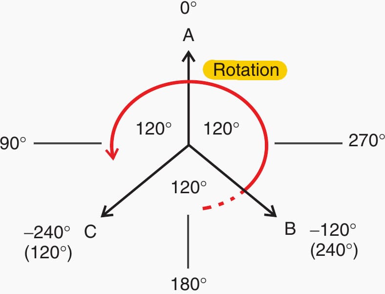
Let us go back and discuss the accepted convention of the phase sequence. The phase sequence phasor diagrams by convention are drawn with vector A pointing up while vector B is on the right following vector A, and vector C on the left following vector B, all in CCW direction. Furthermore, the leading power factor is established as negative and lagging as positive.
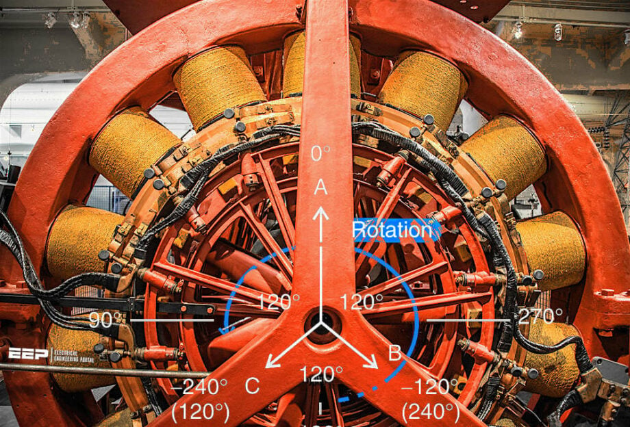
The North American grid phase sequence is CCW as the accepted convention as A ← B ← C, as shown in Figure 2.
Figure 2 – CCW phase sequence
The “Rotation” on the aforementioned graph indicates the stator AC phases or electrical vectors and not the rotor rotation. A professor who commented on this chapter noted that it was wrong to use the term “phase rotation” as is the case in North America and noted in Figure 2.
The rotation should be reserved for the rotors, while the vectors should use the term phase sequence.
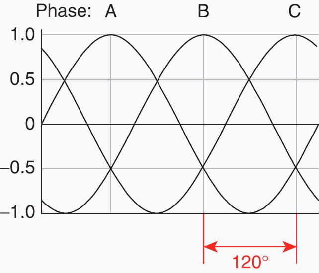
Phase sequence is the order in which the voltage waveforms of a polyphase AC source reach their respective peaks. For a three-phase system, there are only two possible phase sequences:
- CCW: A ← B ← C and
- CW: A → B → C.
The CCW is assumed to be a standard sequence for the discussions as shown in Figure 3.
Figure 3 – Three phase power
If the generator stator phases are wired and laid in sequence ABC and they are subjected to CW rotor rotation (looking from the generator to the turbine), the phase sequence will be CCW. If the rotor turns the other way, the generator phase sequence will be CW.
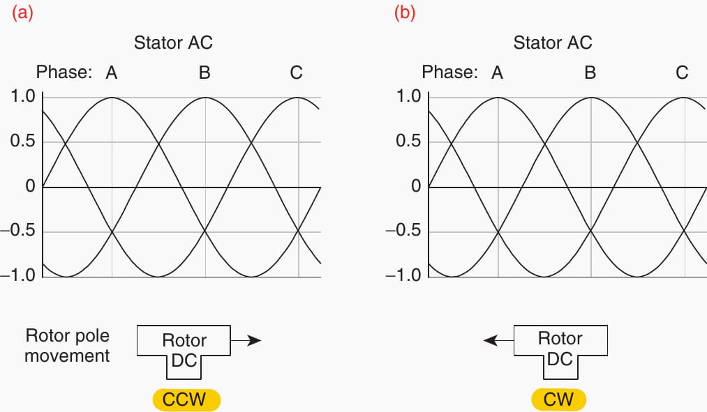
Let us look at it another way. The stator phase bars are stationary, laid out in ABC formation. The rotor turns CW across the bars. It crosses A, followed by B and then C as shown in Figure 4. That causes the CCW phase sequence in the stator winding. Turn the rotor in opposite direction; it causes the CW phase sequence, as shown in a and b.
To change to a desired phase rotation, a change must be done either by:
- Rephasing the order of stator phase bars, or
- By changing the rotor physical rotation.
The fact is there are operating CCW islands within the CW territories and opposite. I am aware of CW islands in the CCW territory, whereby the transmission lines from the CW islands were transposed to match the interconnection with the CCW grid.
Figure 4 – Phase sequence based on rotor rotation
4. Phase Sequence Mistakes
One would think that the manufacturers of the generators would pay more attention to this issue and produce the generators suitable for the plant location but that is not the case. Major and costly errors are often being made.
In the power plants around the world, I have encountered problems in this area, I would say in at least 30% of the plants.
The following examples will highlight the importance of proper design with respect to the system phase sequence and put some light on the prevailing confusion in the power industry:
4.1 Study Case No.1
In Minnesota, a Japanese supplier of a 55 MW generator was warned that, based on the drawings, the generator appeared it had been wired to a CW phasing convention. The supplier answered that the generator was built to CCW convention as it should be.
We checked with an independent engineer, and he was of the opinion that the generator was indeed of CW type.
We cautioned the supplier again, but we were reassured again that everything was correct. The unit was finally installed and energized. The phase sequence was incorrect: →ABC and not ←ABC, as required. The supplier rephased the generator terminations at some cost and made the CW generator to produce a CCW output.
Figure 5 – 55 MW generator
4.2 Study Case No.2
An oil fired 150 MW plant was built in 1953 by a British consultant in Canada. It was built to a CW (British) convention, which was unknown to us. The plant was later integrated into the CCW North American (NA) grid, likely connected through a 230 kV rephased line.
Our company, 50 years later, was asked to add 6 × 35 MW generators to the same plant. The old units were planned to be scrapped.
We set the protective relays to CCW phase sequence as the plant was running on the North American CCW grid. The owner also “confirmed to me” that the old plant is a CCW fully integrated grid operating plant. A week later, during the commissioning of the first unit, the unit was energized, but it tripped after a few seconds. The tripping was happening without a bang or any other trace indication.
Having tried everything to resolve this issue within a whole week without a success, we changed the relays settings to the CW convention. The unit started and stayed on! How do you like that? Then, we decided to check the phase rotation in the old plant. It was CW! How about that?
This was before the synchronizing. Then I asked the generator suppliers to tell me what the generator was built to?
They told me it was CW.
Now, everything became clear! Then they informed us that years back they checked and proved the existing plant was turning as a CW plant and built the generators to CW convention. It was evident that after 50 years, there was no one in the plant who knew that bit of critical information. The plant was operating as a CW island within the CCW grid.
The Japanese contractor thought it was important to check the plant phase rotation before they build the generators. In this case, there were neither delays nor rework on the units, except for the resetting of the relays.
Suggested Course – Generator Protection Course: Concepts, Applications and Relay Protection Schemes
Generator Protection Course: Concepts, Applications and Relay Protection Schemes
4.3 Study Case No.3
Recently, in an Asian country in which we were erecting two 125 MW units, we were aware the grid was operating in CW convention. On the phasing diagram of the new Hydro project, we noted the symbols indicated a CCW convention. The CW convention was confirmed with the local utility as the plant phase sequence and that information was passed to the supplier of the generators.
They immediately changed the phasing diagram on the drawing to suit and promised to comply and have the generator built to CW convention. Or, if late and not possible, they would transpose the 300 kV output cables in the tunnel during the installation.
We faced a huge problem. It was suggested to rephase two phases on the 13.8 kV generator terminals ahead of the 6500 A isolated phase bus. They declined this approach as costly, due to the tightness for space. And the CTs, PTs, and excitation would have to be reterminated too. The biggest problem was that this change would also affect the rotation of all the motors in the plant.
They estimated that the suggested work would require a massive amount of rewiring and software changes and terminations.
Figure 6 – Changes due to phase sequence error
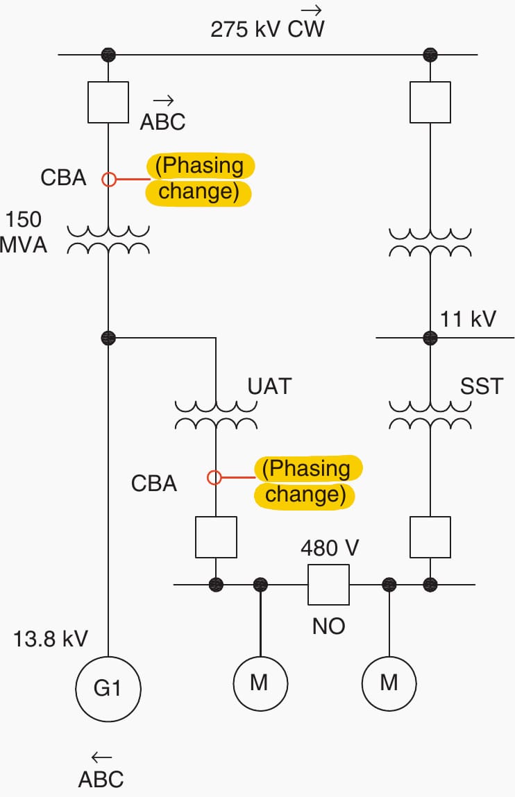
Where:
- UAT = unit auxiliary transformer, and
- SST = station service transformer.
To rephase the 300 kV cables at the 300 kV switchyard was also out of question as one of the 300 kV cable phases was going to be short, and the termination was already filled with special tar that should not be disturbed.
Costly!
The generator protective relays were left set on CCW because the phasing change was executed outside of the differential protection zone.
5. Conclusions
Vector phasing sequence is a confusing issue to all engineers. In some cases, engineers are unsure until the time the unit is energized. By that time, it may be too late to make a change, in particular if the generators are >50 MW. So, what is the reason for such major blunders by the big international manufacturers of the generators?
In my opinion, it is to do with the lack of coordination between the turbine and generator suppliers. These two major pieces of the equipment are likely being assembled in two different and mostly unrelated places. Turbine is made to have a certain direction of physical rotation.
The generator stator on the other hand was assembled with the phase bars laid in either one or the other physical order: ABC or ACB. Either bar laying order can generate a CCW or CW phase sequence that will depend on the turbine physical rotation when it is coupled with the generator. Once the turbine starts turning, the generator rotor will become CCW or CW.
The phase sequence is now determined, and it cannot be changed without a major intervention.
That would indicate the peaking order of the phase sinusoidal waves, as the rotor is cutting the generator phases (bars). This would not necessarily resolve the error in phase sequence if it has already happened, but at least the actual phase sequence would be known ahead of time so other corrective measures can be undertaken earlier.
This suggestion was passed to a generator specialist. The specialist told me that my idea was not the first time he heard it. It was considered, but unfortunately never implemented by the company.
Suggested Study – What is negative sequence current and how does it affect generator work
What is negative sequence current and how does it affect generator work
7. BONUS (PDF): Implementation of Loss-of-Synchronism Protection Systems for Generators
Download Study: Implementation of Loss-of-Synchronism Protection Systems for Generators (for premium members only):
Source: Practical Power Plant Engineering by Z. Bedalov
Related electrical guides & articles


Edvard Csanyi
Hi, I'm an electrical engineer, programmer and founder of EEP - Electrical Engineering Portal. I worked twelve years at Schneider Electric in the position of technical support for low- and medium-voltage projects and the design of busbar trunking systems.I'm highly specialized in the design of LV/MV switchgear and low-voltage, high-power busbar trunking (<6300A) in substations, commercial buildings and industry facilities. I'm also a professional in AutoCAD programming.
Profile: Edvard Csanyi
