
Estimated Study Time: 17 minutes
The essentials of proper selectivity
Selectivity study of a power system is usually considered as an advanced job for advanced engineers, mostly relay protection engineers. This article will try to get close to a few important selectivity principles in a simple manner. It’s important to fully understand that protective devices form a logical system in relation to the power system structure and its earthing system.
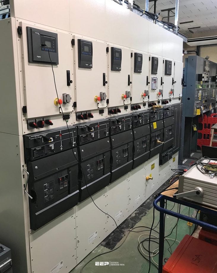 Four ways of ensuring proper selectivity in MV/HV electrical network protection (photo credit: NSS Ltd)
Protective devices are the brain of a power system based on the principle of selectivity that consists of isolating the part of the network affected by the fault, and only that part, as quickly as possible, while all the other unaffected parts of the network remain energized.
There are various ways of ensuring proper selectivity in electrical network protection:
- Time-graded selectivity (using time),
- Logic selectivity (via information exchange),
- Directional protection selectivity,
- Differential protection selectivity.
1. Time-graded selectivity
Time-graded selectivity consists of setting different time delays for the overcurrent protection devices distributed throughout the network. The closer the protection is to the source, the longer the time delay. See Figure 1.
Thus, in Figure 1, the fault shown is detected by all the protection devices (at A, B, C and D). The time-delayed protection at D closes its contacts more quickly than the one installed at C, which in turn reacts more quickly than the one located at B.
Once circuit-breaker D has been tripped and the fault current has been cleared, protection devices A, B and C, through which the current no longer passes, return to standby position.
It takes into account:
- Circuit-breaker breaking time tc
- Time delay tolerances δt
- Upstream protection memory time tm
- Safety margin
∆t must therefore satisfy the relation: ∆t ≥ tc + tm + 2δt + margin (see Figure 2)
For example, for the independent time-phase overcurrent protection devices of the protection relay associated with medium voltage circuit-breakers (see Figure 2):
- tc = 85 ms
- tm = 55 ms | maximum values
- δt = 25 ms
This selectivity system has two advantages:
- It provides its own back-up. Indeed, the protection at C will be activated if the protection at D fails (a healthy part of the installation is cut off);
- It is simple.
Both types of overcurrent protection (independent and inverse time) can be used.
1.1 Time-graded selectivity with independent time overcurrent protection
The protection time delay is constant and independent of the current. The protection tripping curves are shown in Figure 3.

The current threshold settings must be such that:
- Iset, A > Iset, B > Iset, C > Iset, D
- Iset, A > Iset, B > Iset, C > Iset, D : current thresholds of protection devices A, B, C and D.
It is estimated that the accuracy of the measuring unit is 10%. Two successive protection devices must therefore comply with the following relation:
- 0.9 × Iset, A > 1.1 × Iset, B or
- Iset, A ≥ 1.22 × Iset, B
In practice, the following values are taken:
- Iset, A ≥ 1.25 × Iset, B
- Iset, B ≥ 1.25 × Iset, C
- Iset, C ≥ 1.25 × Iset, D
1.2 Time-graded selectivity with inverse time overcurrent protection
The greater the current, the shorter the time delay. The protection tripping curves are shown in Figure 4.

If the current thresholds are set at a value close to In , both protection against overloads and protection against short circuits are ensured. The following values are, for example, taken:
- Iset, A = 1.2 × InA, Iset, B = 1.2 × InB, Iset, C = 1.2 × InC and Iset, D = 1.2 × InD
- InA, InB, InC, InD : nominal currents at the location points of protection devices A, B, C, and D
To ensure selectivity, the protection devices must satisfy the following two conditions:
Condition #1 – The current threshold must be set to at least 25% above the downstream protection threshold:
- Iset, A ≥ 1.25 × Iset, B
- Iset, B ≥ 1.25 × Iset, C
- Iset, C ≥ 1.25 × Iset, D
Condition #2 – The time delay settings are determined in order to obtain the selectivity intervals ∆t = 0.3 s for the maximum current detected by the downstream protection. For example, for the maximum short circuit at D, the time delay at C must be longer than the time delay at D by a value ∆t .
2. Logic selectivity
As we have just seen, time-graded selectivity has some weaknesses. The logic selectivity system has been designed to eliminate these drawbacks. With this system, perfect selectivity can be obtained when tripping occurs, and, furthermore, the tripping time delay of the circuit-breakers located closest to the source is reduced considerably.
When a fault occurs in a radial network, the fault current flows through the circuit located between the source and the fault point:
- a current flows through the protection devices upstream of the fault;
- a current does not flow through the protection devices downstream of the fault;
- only the first protection directly upstream of the fault must be activated.
A protective device able to send and receive a logic standby order is associated with each circuit-breaker. When a fault current flows through the protection, the latter:
- Sends a logic standby order to the protection directly upstream;
- Causes tripping of the associated circuit-breaker if it has not received a logic standby order from another protection.
Figure 5 gives a simplified description of a radial distribution system.
Operation when a fault occurs at A
A fault current flows through protection devices no. 1, no. 2, no. 3 and no. 4.
Protection no. 1 sends a logic standby order to upstream protection no. 2 and a tripping order to circuit-breaker CB1. Protection no. 2 sends a logic standby order to upstream protection no. 3 and receives the logic standby order from protection no. 1, which locks the tripping order of circuit-breaker CB2.
Protection no. 3 sends a logic standby order to upstream protection no. 4 and receives the logic standby order from protection no. 2, which locks the tripping order of circuit-breaker CB3. Protection no. 4 receives the logic standby order from protection no. 3, which locks the tripping order of circuit-breaker CB4.
Circuit-breaker CB1 clears the fault at A at the end of a time interval: tCB1 = t1 + tc, CB1
- t1 – protection no. 1 time delay
- tc, CB1 – circuit-breaker CB1 breaking time
Operation when a fault occurs at B
- a fault current flows through protection no. 1;
- a fault current flows through protection devices no. 2 and no. 3, which then send a logic standby order upstream;
- only protection no. 2 does not receive a logic standby order and sends a tripping order to circuit-breaker CB2.
Circuit-breaker CB2 clears the fault at B at the end of a time interval: tCB2 = t2 + tc, CB2
- t2 – protection no. 1 time delay
- tc, CB2 – circuit-breaker CB1 breaking time
With the logic selectivity system, the fault clearance time can be reduced and is independent of the number of stages. It is possible to obtain selectivity between an upstream protection with a short time delay and a downstream protection with a long time delay, e.g. by setting a shorter time delay at the source than near the loads.
Note! To ensure safety, the logic standby time is limited, thus allowing an upstream protection to operate as back-up of a faulty downstream protection.
Example: mixed selectivity (logic + time-graded)

Operation of mixed selectivity
Logic selectivity is set up between the incoming feeder and the outgoing feeders of each switchboard. The logic link wire costs little since it connects the circuit-breakers or relays to the same switchboard. Between the switchboards, time-graded selectivity is set up, thus avoiding the necessity of installing long logic link wires.
Fault at (1)
The protection devices at F, D and B send a logic standby order to protection devices E, C and A, which may be time delayed to 0.1 second, respectively. The circuit-breaker F is tripped after its time delay of 0.1 second. The non-tripping of circuit-breakers D and B is ensured by time-graded selectivity: tD = tF + 0.3 s and tB = tD + 0.3 s.
In the event of failure of the protection at F or the associated circuit-breaker, the protection at E is activated after the logic standby time, i.e. 0.1 + 0.2 = 0.3 seconds. The 0.4 second time-delayed protection at D is also activated (there is no selectivity between E and D in the event of F failing, unless D’s time delay is increased).
Fault at (d)
The protection devices at D and B send a logic standby order to the protection devices at C and A respectively. The circuit-breaker E is tripped after its time delay of 0.1 second.
Fault at (e)
The protection devices at D and B send a logic standby order to the protection devices at C and A respectively. The circuit-breaker at D is tripped after its time delay of 0.4 seconds.
In the event of failure of the protection at D or the associated circuit-breaker, the protection at C is activated after the logic standby time, i.e. 0.4 + 0.2 = 0.6 seconds. Therefore, using mixed selectivity the time delays can be reduced (roughly by a ratio of 2) without going to great expense, since logic link wires need only be installed between circuit-breakers or relays in the same switchboard.
3. Directional selectivity
In a meshed network, in which a fault is fed by both ends, protection that is sensitive to the direction of the fault current flow must be used in order to be able to locate and clear the fault. To do this, directional overcurrent protection devices are used.
We will give an example of directional selectivity for the phase-to-phase faults in a network with two incoming feeders. See Figure 7.

Circuit-breakers CB1 and CB2 are fitted with directional overcurrent protection devices, whereas CB3 and CB4 are fitted with phase overcurrent protection devices.
For a fault at A:
- The short-circuit currents Isc1 and Isc2 are established simultaneously;
- The directional protection at CB2 is not activated because a current circulating
in the opposite direction to its protection detection flows through it; - The directional protection at CB1 is activated because a current circulating in the same direction as its protection detection flows through it. This causes the circuit-breaker CB1 to be tripped and the current Isc2 is interrupted. An inter-tripping system causes CB3 to open and the current Isc1 is interrupted;
- The protection at CB4 is no longer activated.
For further details about the protection of a network with two parallel incoming feeders, see this technical article:
The art of achieving selectivity between incoming feeders connected in parallel
[be]
4. Selectivity by differential protection
This type of protection compares the currents at the ends of the monitored network section (see Figure 8). Any difference between these currents indicates the presence of a fault. The protection reacts only to faults inside the monitored zone and is insensitive to any external fault. It is thus self-selective.
The equipment protected may be:
- a motor;
- a generator;
- a busbar;
- a cable or line;
- a transformer.
This type of protection has the following characteristics:
- It can detect fault currents lower than the nominal current;
- The time delay may be short, if not zero, since the selectivity is based on the detection and not on the time delay.
A detailed explanation of differential protection operation is given in the technical articles:
The essentials of LV/MV/HV substation bus overcurrent and differential protection
Power transformer protection relaying (overcurrent, restricted earth fault & differential)
Sources:
- Protection of Electrical Networks by Christophe Prévé
Related electrical guides & articles


Edvard Csanyi
Hi, I'm an electrical engineer, programmer and founder of EEP - Electrical Engineering Portal. I worked twelve years at Schneider Electric in the position of technical support for low- and medium-voltage projects and the design of busbar trunking systems.I'm highly specialized in the design of LV/MV switchgear and low-voltage, high-power busbar trunking (<6300A) in substations, commercial buildings and industry facilities. I'm also a professional in AutoCAD programming.
Profile: Edvard Csanyi

Kindly send more conceptual thing about on power systems protection, transmission distribution,EHT , HT LT lines, generation, PCC, MCC etc