
Estimated Study Time: 18 minutes
The basics of protection and control
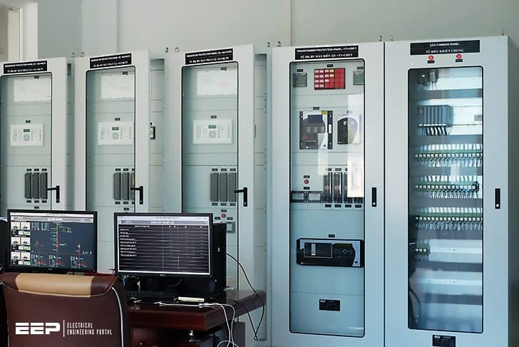
This technical article discusses some of the basics of protection and control as successfully used for decades. Majority of these general requirements will have to be retained by new communication-based solutions. It is important to distinguish between the key need, and the present way of accomplishing the need (current implementations are ways of meeting functional requirements, not the functional requirements themselves).
 Solving the architectural and reliability puzzle of a protection and control system
While users will have to re-think and adapt to different ways of accomplishing the basic requirements, architects of the new systems must factor in all the basic principles that constitute the protection and control engineering field.
This article touches on several key aspects in a simple arbitrary benchmark (Figure 1) for discussing both the principles and some of the new solutions.
This technical article represents some of the really important observations in awesome work “IEC 61850 – A practical application primer for protection engineers” that protection engineers and other involved in protection & control design should pay attention.
Contents:
- Zones of protection
- Allocation of IEDs to zones of protection
- Allocation of protection & control functions to IEDs
- AC signals
- DC signals
- Reliability and availability of protection
1. Zones of protection
The zone of protection refers to that primary equipment for which faults are detected by a given protection scheme. The protection scheme is defined by the relays and their measuring CTs and VTs. Interrupting devices (circuit breakers, circuit switchers, etc.) that are operated by the protection scheme must be arranged remove all sources of energy from within the protection zone.
Ideally, a protection zone is confined to a single primary device such as a transformer or a bus. Limitations on the location of instrument transformers and interrupting devices may result in larger zones.
Protection zones must overlap in order to provide coverage for all primary equipment. This typically results in breakers falling into multiple zones.
2. Allocation of IEDs to zones of protection
Typically an IED or relay is dedicated to the protection of a single zone. In this way a failure of this device or its algorithms compromises a single zone. IEDs may provide backup protection to other zones. In this case coordination is often required.
Redundant protection generally provides increased reliability and shorter clearing time when compared with backup protection at the expense of increased cost and complexity.
Redundant protection also allows one lED to be taken from service for maintenance while the primary equipment remains in-service, protected by the other IED.
The requirement to keep primary equipment in-service also affects the topology of the substation itself.
For instance 1½ breaker, ring bus, or double bus configurations are often implemented at higher voltage levels. In these cases it may be useful to allocate IEDs to breakers as well as to protection zones.
The breaker IED is responsible for:
- Breaker failure,
- Auto-reclosure,
- Synchronized closing and
- Interlocking.
In future, the breaker IED could be considered to be the sole interface point for all protection and control functions associated with the breaker, including SCADA.
Routine maintenance can be carried out on each of the redundant line protections (one at a time) with all primary equipment in-service.
Additionally each breaker and its associated IED can be taken from service (one at a time) for maintenance purposes. There is a value in separating protection functions and keeping them aligned with the zones of the primary equipment.
3. Allocation of protection & control functions to IEDs
Conventional protection schemes were initially developed using good old electromechanical relays. These devices often performed one or two functions only on a per-phase basis. While these schemes required a lot of panel space and wiring, they also benefited from inherent redundancy.
For example, a feeder scheme could consist of three single-phase Time overcurrent (TOC) and Instantaneous overcurrent (IOC) relays and a ground IOC/TOC relay. This meant that 2 relays were expected to operate for many fault types (with the exception of a low magnitude ground fault).
Historically, functions were separated within one protection group because there was no other choice. Integrating functions within a group doesn’t necessarily lessen reliability in a fully-duplicated scheme because common failures have always existed.
For another example one can consider again the line terminal shown in Figure 2. Traditionally the functions shown in the breaker IED (synchrocheck, auto-reclose, and breaker failure) were not duplicated.
Another consideration is the potentially large tripping exposure to a malfunction. It is probably warranted to duplicate these functions in both IEDs.
However, this approach may require careful consideration. For example, allowing two auto-reclose schemes to operate in parallel could lead to unexpected and unwanted behavior especially for single-pole tripping.
4. AC signals
Most protection schemes utilize voltages and currents measured via conventional CTs and VTs. CTs typically have nominal secondary current ratings of 1A or 5A. VTs typically have nominal secondary phase-neutral voltage ratings of 57V to 120V.
CTs may serve several IEDs wired in series. If so, the protection designer needs to consider the consequence of a failure of a cable or CT on the overall scheme.
The IEDs of redundant systems are often fed from separate CTs. The cabling may be routed over different paths for additional redundancy. If the redundant IEDs share the same panel, the cabling may then terminate on different sides of the enclosure.
Almost all protection applications require their input AC signals to be time-aligned. This calls for synchronization of measurements of these signals, either with respect to one another or with respect to the absolute time.
Today, this requirement is achieved by bringing all signals into a single lED and processing them synchronously within the device with respect to an internal arbitrary time scale.
With the exception of some line current differential applications, protection functions today do not depend on any external time synchronization source.
5. DC signals
Protection schemes often utilize signals from other schemes or from field devices (circuit breakers, etc.). Contacts are brought in from the station battery to feed auxiliary relay logic or the inputs of IEDs.
In large stations, miles of control cabling are sometimes required to route these signals. As such, station batteries are typically ungrounded and are equipped with battery ground detection in order to allow station personnel to detect and repair cable faults. Even so, incorrect status information due to faulty circuitry is inevitable and must be planned for in the design.
In general, a protection scheme should not produce a critical response (i.e. trip a breaker) based solely on a status input.
In applications where this principle cannot be adhered to, the scheme should use multiple status signals for additional security.
For example, a scheme that uses both the normally open and normally closed breaker status contacts can be designed to discriminate between correct and abnormal indication.
In the redundant systems the signals for each scheme are usually derived from different devices or field contacts. These signals are segregated onto separate cables. The cables may be routed via different paths within the station. In very critical stations there may be separate batteries for the redundant systems. This reduces the system exposure to battery grounds.
Critical DC signals such as trip, close or breaker failure initiate can be equipped with test facilities to allow safe isolation of those signals from the rest of the system.
6. Reliability and availability of protection
Availability and reliability of protection are not impacted when using microprocessor-based protective relays as known today, and applied to both protection and control within the SCADA realm of the IEC 61850.
When pursuing distributed architectures based on the concept of a process bus with the intent of eliminating copper wiring in the yard and replacing it with fiber optics solution, availability and reliability of protection is a fundamental consideration, and one of the key barriers to overcome.
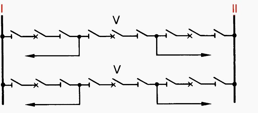
The figure clearly illustrates the reason for extensive field wiring: redundancy and overlapping protection zones.
Figure 7 presents a hypothetical architecture in which each AC signal is digitized by a separate merging unit. Separate MUs are used to provide for the DC signal interface (MU-11 through 14). The A&B systems are kept separate. Consider the availability of the LINE 1 protection system A.
This zone depends on availability of MUs 1, 8, 10 for measurement and MUs 11 and 14 for tripping, Ethernet LAN A for communications, and Line IED for overall processing – not to mention the time synchronization source for the AC related MUs 11,8 and 10).
Composed out of seven of today’s IEDs such a line protection system would have an MTTF on an order of magnitude lower compared with today’s relays (see Annex B).
Figure 8 presents a sample architecture with one breaker IED (MU) that interfaces two currents and DC signals. Now only two MUS per breaker are required. Still the line protection is a system involving five IEDs IMUs 1, 3, 6, Ethernet switch, IED).
Note that the BF function depends on three devices (MU-1, LAN A, BF IED). This becomes a flaw that reduces dramatically availability of the BF function, and calls for solutions in a form of redundant hardware, or equivalent.
Figure 9 further eliminates MUs 5 and 6 by wiring the voltage signals to MU-3 and 4 (typically a relatively short distance compared with the distance from the yard all the way to the control house). Still the line protection depends on four IEDs or five counting the time synchronization source.
MUs 3 and 4 become equivalent to today’s microprocessor-based relays in complexity. They support current and voltage inputs as well as digital inputs and output contacts.
The question arises:
Why not provide the complete functionality in such a yard device, eliminating the need for all the other IEDs.
The obvious acceptance and maintenance issues may be easier to overcome compared with the solutions of Figures 3 through 6. It is strongly recommended that concepts building around the process bus and substituting copper with fiber, particularly for the yard wiring, are presented in the context of actual count of CT, VTs, giving consideration to overlapping protection zones, redundancy and separation of the A&B systems.
Once the architecture is presented, an IED count can be approximated, and reliability study should be conducted in order to validate the solution.
A process bus protection system set up with off-the-shelf components (merging units fed from non-conventional instrument transformers, explicitly synchronized via their IRIG-B inputs, and communicating via Ethernet network) would have reliability numbers decimated by an order of magnitude compared with today’s microprocessor-based relays.
This is because of substantial increase in the total part count and complexity of such a distributed system as compared with today’s integrated microprocessor-based relays.
It is quite obvious that the interoperability protocols of the IEC 61850 in the areas of process bus and peer-to-peer communication are of little help in solving this architectural/reliability puzzle.
Sources:
- IEC 61850 – A practical application primer for protection engineers by Bogdan Kasztenny, James Whatley, Eric A. Udren, John Burger, Dale Finney and Mark Adamiak
Related electrical guides & articles


Edvard Csanyi
Hi, I'm an electrical engineer, programmer and founder of EEP - Electrical Engineering Portal. I worked twelve years at Schneider Electric in the position of technical support for low- and medium-voltage projects and the design of busbar trunking systems.I'm highly specialized in the design of LV/MV switchgear and low-voltage, high-power busbar trunking (<6300A) in substations, commercial buildings and industry facilities. I'm also a professional in AutoCAD programming.
Profile: Edvard Csanyi
