
Estimated Study Time: 10 minutes
Electrified Railways – The concept
Many regional, urban and high-speed inter-urban rail networks worldwide are electrified, to provide the motive power for trains (Figure 1).
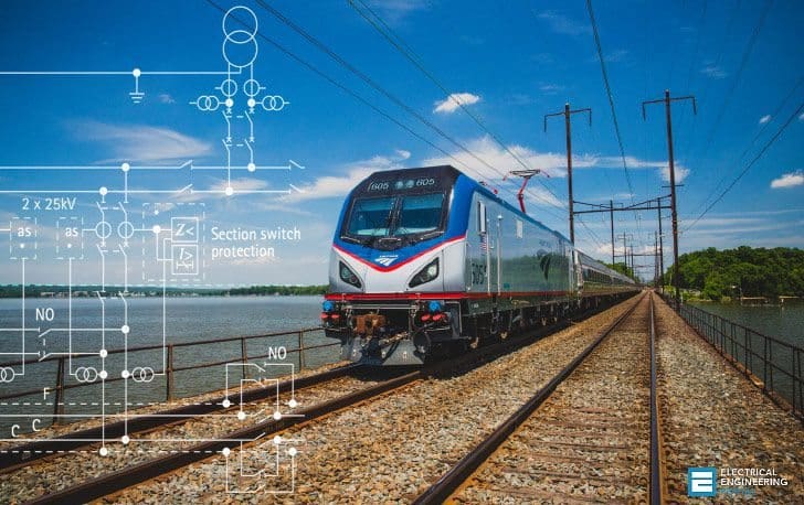 Protection of A.C. Electrified Railways (on photo: Amtrak Regional trains on most complex, and most technically advanced rail systems in the world, with over 2,000 trains on Amtrak-controlled segments each weekday; credit: Chuck Gomez via Flickr)
The electrification system serves as the contact interface for current collection by each train, and in A.C. electrified railways as the means to distribute power.
The latter arrangement is most commonly used for D.C. traction, while the former arrangement is used for A.C. and D.C. traction. Some rail routes have dual overhead and conductor-rail electrification to facilitate route sharing by different rail operators.

Overhead catenaries are generally considered to be safer, as they are above the track, out of reach of rail personnel and the public. They are the only way in which a traction feed at high voltages can be engineered. They provide a single-phase A.C. supply with a voltage in the range of 11kV-50kV with respect to the running rails, although 1.5kV and 3kV D.C. catenaries are predominant in some countries. When a conductor-rail system is used, the supply voltage is generally 600V to 1700V D.C.
This technical article generally introducuse the protection associated with HV overhead A.C. catenary electrification. Due to the nature of many rail routes and the limited electrical clearances (especially where an existing non-electrified route is to be electrified), catenary faults are common.
A typical fault rate is one fault per year per route kilometre of track. The relatively high fault rate, coupled with the high mechanical tension in the contact wire (typically 6- 20kN) demands fast fault clearance. Should a fault not be cleared quickly, the conductors that form the catenary may break due to intense overheating, with the consequent risk of further severe damage caused by moving trains and lengthy disruption to train services.
Protection philosophy //
The application of protection to electrical power transmission schemes is biased towards security whilst ensuring dependability only for the most severe faults within the protected circuit. Being too adventurous with the application of remote back-up protection should be avoided, since the consequences of unwanted tripping are serious.
Fallen live wires caused by mechanical damage or accident represent a greater safety hazard with railways, due to the higher probability of people being close by (railway personnel working on the track, or passengers). Traction unit faults are a fire hazard and a safety risk to passengers, especially in tunnels. For these reasons, there will be a bias towards dependability of back-up protection at the expense of security.
The consequences of an occasional unwanted trip are far more acceptable (the control centre simply recloses the tripped CB, some trains are delayed while the control centre ensures it is safe to reclose) than the consequences of a failure to trip for a fallen wire or a traction unit fault.
Classical single-phase feeding
Classical single-phase A.C. railway electrification has been used since the 1920’s. Earlier systems used low frequency supplies and in many countries, electrification systems using 162/3Hz and 25Hz supplies are in use. The cost of conversion of an extensive network, with a requirement for through working of locomotives, throughout the necessary changeover period, is usually prohibitive.

Starting from Western Europe and with the influence spreading worldwide, single-phase A.C. electrification at the standard power system frequency of 50/60Hz, has become the standard.
Figure 2 above illustrates classical 25kV feeding with booster transformers (BT). The booster transformers are used to force the traction return current to flow in an aerially mounted return conductor, anchored to the back of the supporting masts (Figure 3).
A step-down transformer connected phase to phase across the Utility grid is generally the source of the traction supply. The electrical feed to the train is via the overhead catenary, with the return current flowing via the rails and then through the return conductor.

As the running rails are bonded to earth at regular intervals, they are nominally at earth potential. A single-pole circuit breaker is all that is required to disconnect the supply to the catenary in the event of a fault.
Classical System // Feeding Diagram
In practice, single-track railway lines are rare, and two or four parallel tracks are more common. The overhead line equipment is then comprised of two or four electrically independent catenaries, running in parallel. Figure 4 shows the feeding diagram for a typical two-track railway using a classical electrification system.

The infeed to the tracks in the ‘northbound’direction is via grid transformer T1 at the Feeder Station (FS). The power is then distributed via catenaries A and B above the northbound and southbound tracks. At intervals, it is usual to parallel the two catenaries at paralleling/subsectioning substations, as illustrated in the Figure 4.
Load current can then flow in the parallel paths, which reduces the impedance to the load and hence the line voltage drops. As the substation terminology implies, the provision of circuit breakers for each of the outgoing feeds to the catenaries also allows subsectioning –i.e. the ability to disconnect supply from sections of catenary, in the event of a fault, or to allow for maintenance.
The infeed from T1 generally feeds only as far as the normally open bus section circuit breaker (BS2) at the mid-point substation (MPSS). Beyond the MPSS there is a mirror image of the electrical arrangements T1 to BS2 shown in Figure 4, with the remote end feeder station often 40-60km distant from T1. BS2 must remain open during normal feeding, to prevent Utility power transfer via the single-phase catenary, or to avoid parallelling supplies that may be derived from different phase pairs of the Utility grid –e.g. Phase A-B at T1, and B-C at the next FS to the north.
The same is true for BS1, which normally remains open, as the T1 and T2 feeds are generally from different phase pairs, in an attempt to balance the loading on the three phase Utility grid. The neutral section (NS) is a non-conducting section of catenary used to provide continuity of the catenary for the pantographs of motive power units while isolating electrically the sections of track.
While only two (one per rail track) are shown for simplicity, separating the tracks fed by T1 and T2 at the Feeder Station, they are located at every point where electrical isolation facilities are provided.
Japan Railroad – Overhead Train Power Line
Reference // Network Protection and Automation Guide – Areva
Edvard Csanyi
Hi, I'm an electrical engineer, programmer and founder of EEP - Electrical Engineering Portal. I worked twelve years at Schneider Electric in the position of technical support for low- and medium-voltage projects and the design of busbar trunking systems.I'm highly specialized in the design of LV/MV switchgear and low-voltage, high-power busbar trunking (<6300A) in substations, commercial buildings and industry facilities. I'm also a professional in AutoCAD programming.
Profile: Edvard Csanyi

Very good u tube lecturers, and I suggest to make some ppts and animated ppts with download fecility please
I own an innovative solution train and its infrastructure better than existing in the world when it comes to speed, security, building its stock …