
Estimated Study Time: 19 minutes
Introduction to protective relays
Protective relays are most often applied with other protective and auxiliary relays as a system rather than individually. The following basic scheme descriptions apply to electromechanical, static, and microprocessor relay systems. The static and microprocessor relay systems generally have more elaborate logic involved in the tripping decision, particularly in the area of transient blocking during external fault clearing.
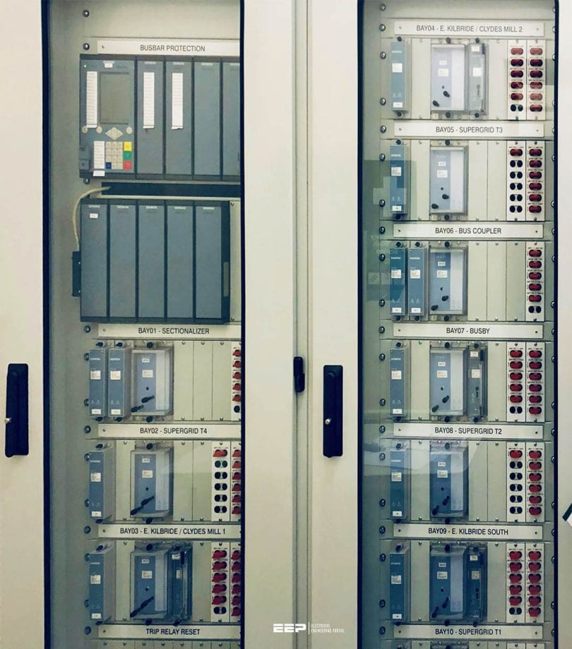 Protection practice recommendations and relay schemes for transformer, bus and breaker failure (photo credit: Liam Maher via Linkedin)
Static systems require more careful treatment of input circuits, i.e., CT and VT leads are often shielded. Static systems are slightly faster, require less maintenance, and are considerably more costly than the electromechanical systems.
Microprocessor relays are very versatile and often can perform many functions at a lower cost than other methods. In addition to basic relaying they may do fault locating, fault data recording, self testing, and metering.
Since microprocessor relays tend to have more protective functions available in a relay case, it often allows the relay engineer to provide additional protection the relay engineer would not have previously considered. Microprocessor relay systems tend to have fewer devices since they contain more functions in one case. This will tend to reduce the cost of initial installation.
1. Transformer and Reactor Protection
Transformers are protected by fuses or circuit-interrupting devices such as breakers or circuit switchers with relays detecting faults and providing trip signals to the circuit-interrupting devices.
Transformers 5 MVA and below are almost always protected by fuses. Relay protection of transformers is most often used for transformers rated 10 MVA and above although there are transformers up to 30 MVA that are protected by fuses.
Fuses will provide protection for primary and secondary external faults, but little protection for transformer internal faults. Fuses introduce the probability of creating a severely unbalanced (single-phasing) voltage condition for secondary loads should only one fuse blow.
Proper coordination with secondary devices is essential to avoid this condition.
Good reading on relay coordination:
Achieving Relay Coordination and Selective Short Circuit Protection In Transmission Networks
Relay protection for the larger size transformers usually includes sudden pressure relays, differential relays, overcurrent relays or directional phase distance relays, and ground overcurrent relays.
See Figure 2 below.
Sudden pressure relays are often considered by many to be the primary relay protection on a transformer. The sudden pressure relay is sensitive to the sudden changes in pressure in the transformer tank that occur during an internal fault.
Differential protection is a primary scheme of protection that is normally applied on a percentage differential basis to allow for differences in transformer ratios, magnetizing current, and current transformer mismatch.
Overcurrent relays are often applied on the primary voltage winding to provide backup protection to the differential relay protection. If the overcurrent relays may not be coordinated with the secondary main and feeder relays, a directional phase distance relay may be applied
A ground overcurrent relay is normally applied to provide increased sensitivity to ground faults.
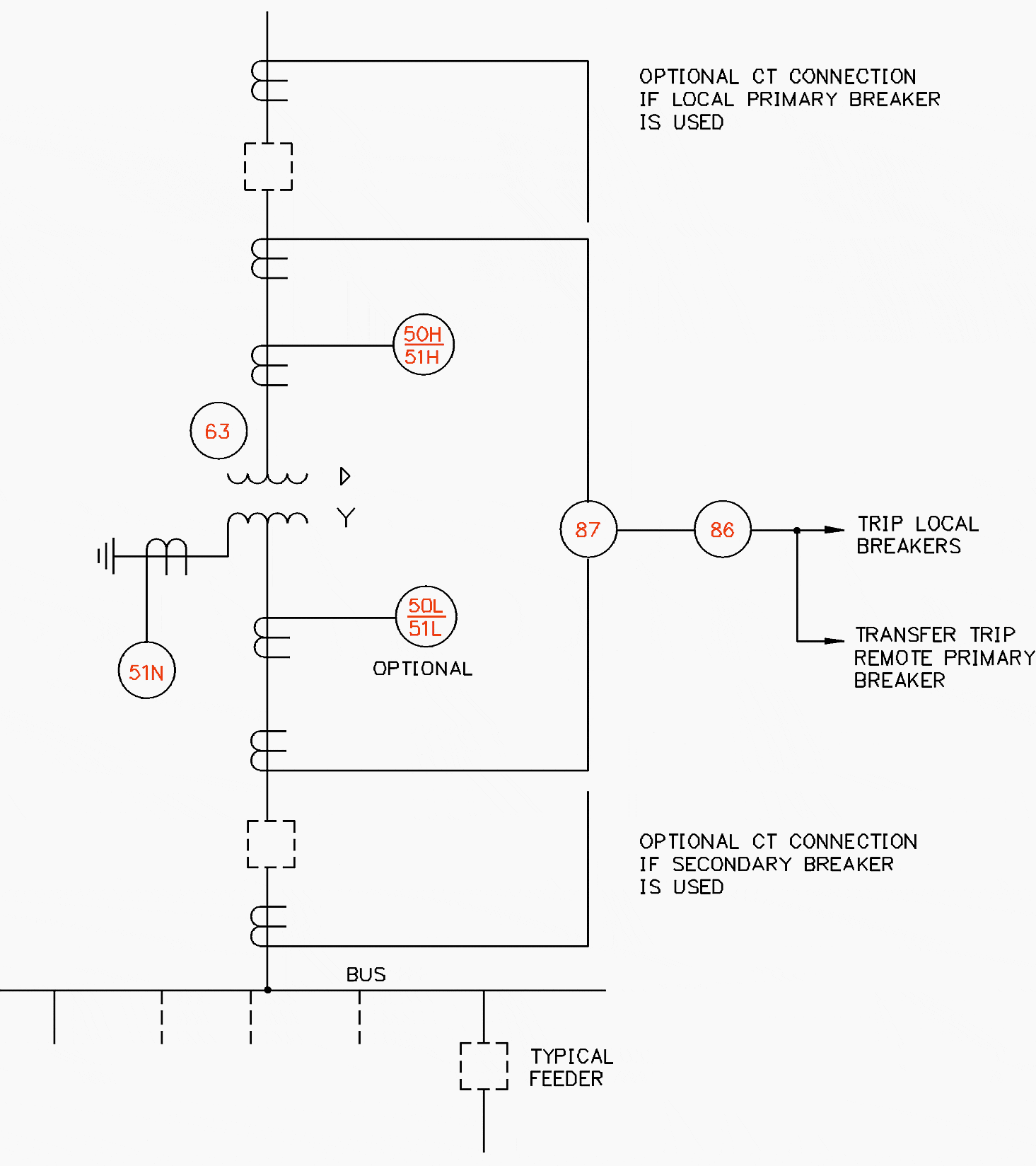
Figure 2 indicates the possibility of using local primary and secondary breakers. Because of economics, a primary breaker is sometimes not used. Tripping of the transformer is accomplished by sending a transfer trip signal to the remote substation using a communications signal or a high-speed ground switch. The time required to isolate the transformer is increased by the communication channel time or the time for the remote relay and breaker to clear the fault established by the high-speed ground switch. Secondary breakers are often not used.
The engineer will have to decide whether or not to trip all the feeder breakers or to manually open the feeder breakers before re-energizing the transformer.
Reactors may be protected by generator-type differential relays with phase and ground overcurrent backup relays. Occasionally, phase distance relays are used for backup.
Thermal relays provide additional protection for the transformer against internal heating as a result of overloading the transformer. Each transformer installation should be individually evaluated for the type of protection that is to be applied.
2. Bus Protection
2.1 Remote Tripping for Bus Fault
Short-circuit faults on buses can be isolated by allowing remote substation breakers on all lines that feed into the faulted bus to trip by Zone 2 or time-delay ground relay. This type of bus protection is simple and the most economical. It has the disadvantage that any loads fed by lines to the remote substations are also removed from service.
Another disadvantage is that the time necessary to clear the fault may be intolerable.
2.2 Local Tripping for Bus Fault
In distribution substations, the bus protection is often provided by overcurrent relays, phase and neutral, located on either the low-voltage or high-voltage side of the transformer. See Figure 2. The phase relays have to be set to coordinate with the feeder relays and any additional downstream devices. This results in a slow trip time for the clearing of the bus.
Short-circuit faults can be removed by a bus protective scheme in which all the substation breakers associated with a faulted bus are tripped.
The two basic types of bus protective schemes are:
- Current differential and
- Voltage differential.
The current differential scheme connects all the current transformers on all the circuits connected to a bus in parallel, and the relays operate on the unbalanced current that exists during fault conditions. See Figure 3.

During normal conditions, there should be no unbalanced current, since the current entering a bus has to equal the current leaving a bus. Restraint coils help to compensate for unequal current transformer performance during external faults, but the scheme still has to be applied carefully on buses with high short-circuit capabilities.
Voltage differential schemes use the same parallel connection but connect a high-impedance voltage element across the parallel. It is possible to set this voltage element well above the worst case external fault voltage and still retain adequate sensitivity for internal faults.
This type of relay performs well on buses with high short-circuit capability.
Many times this time delay is unacceptable for the coordination with the rest of the system relays.
Microprocessor relay normally provides many additional functions at a relatively inexpensive cost, and some of them is a pseudo bus differential scheme that can be been applied. This scheme uses a combination of instantaneous relay elements from the secondary main bus relay and the feeder relays to detect whether the fault is on the feeder or on the bus.
See Figure 4.

This scheme requires that there be no fault sources on the feeders since the operation of the feeder instantaneous elements for reverse feeder current would make the fault look like a feeder fault and cause the scheme to fail.
If fault sources are located on the feeders, directional instantaneous overcurrent relays have to be used. An instantaneous element is used on the main breaker relay with a setting that is ensured to pick up any bus fault. The instantaneous elements of the feeder relays have to be set to reach out farther than the main breaker relay so that, for any close-in feeder fault that the main breaker relay will see, the feeder relay will also see and disable the circuit.
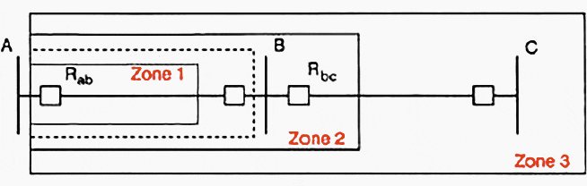
Local tripping for a bus fault may be accomplished by the use of a reverse-looking Zone 3 element from a distance relay. Zones 1 and 2 on a line are set to look out on the line, away from the bus. Often, the Zone 3 element is set to look in the reverse direction, which will see the bus behind it. Through a timer, the Zone 3 may be set to trip through-bus faults.
3. Breaker Failure Protection
Breaker failures can normally be separated into two classes:
- The failure of the breaker itself and
- The failure of the relaying associated with the breaker.
Schemes developed to protect for the failure of breakers are based on providing either remote backup or local backup. Failure of the breaker results in the necessity to trip all the adjacent breakers in order to clear the fault and to isolate the failed breaker.
3.1 Remote Backup
Remote backup normally consists of a Zone 3 distance relay and/or ground time overcurrent relay set to cover lines contiguous to the line being protected. This scheme will provide protection for breaker failure regardless of whether the failure is a result of relay failure or breaker failure. It will normally see faults on the protected line plus faults on the next bus and line adjacent to the protected line.
This scheme has the advantage of simplicity.
When applied on a system where the adjacent bus has a number of lines with varying length, the settings for the relay may extend beyond the adjacent lines resulting in overcoverage and overtripping. When adjacent lines are multi-terminal lines, a number of terminals may be unnecessarily tripped by remote backup.
Longer reach Zone 3 relays are more susceptible to out-of-step system swings. Even with its shortcomings, in some situations with its inherent economics, this scheme may provide acceptable backup performance.
3.2 Local Backup
A simple means of providing local backup protection is to use the Zone 3 relay looking in the reverse direction. This provides a degree of protection for local equipment including all adjacent breakers, bus, lines, and remote terminals.
Advantages and disadvantages in the use of this scheme are included in the discussion above on remote backup.
An additional means of providing breaker protection is to add timing to the primary relays. If the relays do not trip and the fault is still on the system within the set time of the timer, the timer will act to trip all adjacent breakers. This scheme depends on the proper action of the primary relays and provides no backup to the failure of those relays.
An additional scheme provides the use of a second set of relays to back up the primary relaying. Carried to the maximum limit, a second DC tripping system is provided including battery, panels, charger, relays, breaker trip coils, CTs, and potential devices.
The reduced cost of relaying afforded by the development of microprocessor relays makes this option a relatively economical option to provide backup protection for relays. This scheme does not provide for the tripping of adjacent breakers in the case of the failure of the breaker mechanical mechanism to trip the breaker and clear the fault.
3.2.1 Full breaker failure backup
Full breaker failure backup includes protection for the failure of relays and the failure of the breaker. A separate backup relay that acts to trip all adjacent breakers, including remote breakers by means of a transfer trip, provides this degree of backup.
Figure 6 indicates a typical configuration for a local breaker failure relay. Indicated are primary and secondary relays, dual trip coils in the breaker, and the fault detector and timer associated with the breaker relay.

Should either the primary or secondary relay call for a trip of the breaker, an auxiliary relay, 62X or 62Y, keys the timer. If the fault is not removed during the setting for the timer, the 86 BF lockout relay is picked up to trip all adjacent breakers and transfer trip any remote breakers.
The time setting for the timer is usually in the range of 10 to 20 cycles. If either the protective scheme resets or the current relay drops out within the set time, nothing happens.
Sources:
- Design Guide for Rural Substations by United States Department of Agriculture
Related electrical guides & articles


Edvard Csanyi
Hi, I'm an electrical engineer, programmer and founder of EEP - Electrical Engineering Portal. I worked twelve years at Schneider Electric in the position of technical support for low- and medium-voltage projects and the design of busbar trunking systems.I'm highly specialized in the design of LV/MV switchgear and low-voltage, high-power busbar trunking (<6300A) in substations, commercial buildings and industry facilities. I'm also a professional in AutoCAD programming.
Profile: Edvard Csanyi

I read all your articles regularly but only over view because I has no your premium membership. I know your articles are based on authentic research by field experts and you have a right of paid content.
If it possible there should be discount in your paid content.
Indian writers are requested to write technical articles in clear & understandable English instead of confusing it.
Regards
HOW to calculate relay setting
Need each type of protection on generator with detailed explanation and setting calculation
Hello I want to know if you with certified training?
50, 51L & H. The relay numbers given in case of differential protection are not as per ANSI. This new term is derived from where? Neither it is indicated – explained in description.