
Estimated Study Time: 9 minutes
System description
Connections of private substations to utilities are made more complicated with the addition of private-owned generation facilities. The choice of relays and their placement must be made to ensure adequate protection of both the generator and the interface.
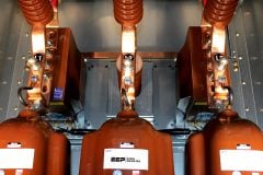
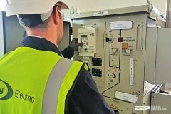
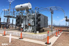
 Protection scheme for remote private substation with small generator (photo credit: Stuart Watts via Linkedin)
The protection of small generators will be accomplished by a minimal investment in relay protection. Large generators require a full complement of generator relays (see IEEE Std C37.102TM).
In addition, the location of larger generators on the utility system may not be optimized for large power flows or bidirectional flow and may require changes to the utility transmission system.
Figure 1 is an example of a small generator connected to a private substation in a simple configuration. The example shows the generator connected to a low-side bus in parallel with a consumer load, which is typical of a small unit.
Where:
| Label (ANSI) | Description | Label (ANSI) | Description |
| 52 | Circuit breaker / Circuit switcher | 50 | Phase-instantaneous overcurrent relay |
| C.S. | Circuit switcher | 50N | Ground-instantaneous overcurrent relay |
| 32 | Directional power relay | 51 | Phase-time overcurrent relay |
| 27 | Undervoltage relay | 51G | Transformer neutral overcurrent relay |
| 59 | Overvoltage relay | 51N | Ground-time overcurrent relay |
| 59G | Zero sequence overvoltage relay | 87B | Bus differential relay |
| 87T | Transformer differential | 81-O | Over-frequency relay |
| 63 | Transformer sudden-pressure relay | 81-U | Under-frequency relay |
The low-side wye connection of the transformer provides a ground point to the customer load even if the generator is disconnected. The disadvantage is in the fact that operation of remote utility substation breakers may isolate this substation with part of the utility system that leaves the high-voltage system ungrounded.
Steps taken to ensure that this generator can be removed from high-side faults are discussed in Section 3 (Protection of the supply line).
Detecting ground faults is not a problem with large generators because they are usually installed with their own wye-delta transformer, are separate from the consumer load, and are protected by high-voltage breakers.
- Transformer protection
- Transformer low-side bus and feeder protection
- Protection of the supply line
- Synchronizing
1. Transformer protection
The example in Figure 1 shows a transformer protected by:
- Differential (87T),
- Sudden-pressure (63),
- High-side overcurrent (50/51), and
- Neutral ground (51G) relays.
With a smaller transformer, the circuit switcher and the differential relays could be replaced with high-side fuses and the overcurrent relays (50/51) moved to the low side of the transformer.
2. Transformer low-side bus and feeder protection
The low-side bus can be incorporated in the protective zone of the transformer differential relays (87T). If the generator has sufficient capacity to carry the plant load when separated from the utility system, the transformer differential zone can be limited to the transformer and a set of bus differential relays (87B) installed as shown on Figure 1.
The settings on these back up relays must be coordinated with the overcurrent relays, which protect the feeder (50/51) and (50N/51N).
3. Protection of the supply line
For this example protection scheme, the emphasis will be to ensure that the generator will be separated from a supply line fault.
A simple solution to supply line protection is to apply direct transfer trip from the utility substation. This can be a costly option that does not reduce the need for relays at the local substation. When the consumer does not supply power to the utility, a directional power relay (32) can be used that will operate for any power flow to the utility system.
If the utility buys power from the consumer, however, the reverse power relay cannot be used.
Additional phase and ground fault relays may also be required depending on the size of the unit. For instance, in the example shown on Figure 16, zero-sequence voltage relays are required to detect high-voltage ground faults because the transformer has a high-side delta connection.
It should be noted, however, that temporary ground faults on the utility line may not be cleared by the zero-sequence overvoltage relays (59G). Assuming no other ground sources on the utility line, a temporary ground fault on the supply will self extinguish once the remote utility breaker (52-1) opens unless there is sufficient system capacitance to maintain the arc.
This can occur before the 59G relay operates because it will normally have a time delay, in which case the consumer’s substation will not be separated from the supply line.
If there is unchecked automatic reclosing at the utility terminal, there is a risk of closing out-of-phase with the possibility of generator damage.
4. Synchronizing
In most cases, the consumer is responsible for the operation of any non-utility private generation, including returning the system to normal following a planned or inadvertent outage. Operating procedures for energizing the system and synchronizing the non-utility generator must, however, be established jointly with the utility to meet the requirements of both parties with respect to safety, reliability, and operating flexibility.
These procedures should be used in conjunction with interlocks and check relays as required, to minimize possible operator errors.
For the example shown on Figure 1, both Breakers 52-3 and 52-4 should be equipped with facilities to synchronize the non-utility generator to the system.
This permits the following procedures:
- Breakers 52-1, 52-3, and Circuit Switcher 52-2 should trip for any fault on the supply line.
- Breaker 52-1 should be closed once it is confirmed that the line is de-energized.
- Circuit Switcher 52-2 may be closed if Breaker 52-3 is open.
- If the non-utility generator is in service and Bus 1 is energized, then Breaker 52-3 may be synchronized and closed by the consumer.
- If Bus 1 is de-energized and Breaker 52-4 is open, Breaker 52-3 may be closed. The consumer may bring the generator on-line by synchronizing and closing Breaker 52-4.
A similar procedure would be used following a planned outage.
Source: IEEE Std C37.95 – IEEE Guide for Protective Relaying of Utility-Consumer Interconnections
Related electrical guides & articles


Edvard Csanyi
Hi, I'm an electrical engineer, programmer and founder of EEP - Electrical Engineering Portal. I worked twelve years at Schneider Electric in the position of technical support for low- and medium-voltage projects and the design of busbar trunking systems.I'm highly specialized in the design of LV/MV switchgear and low-voltage, high-power busbar trunking (<6300A) in substations, commercial buildings and industry facilities. I'm also a professional in AutoCAD programming.
Profile: Edvard Csanyi

66 kv substation, 10ma transformer
Hello Edvard, why the CT for 87G not placed in between Generator winding and Neutral Point (NGR)? How 87G detects a fault occures inside of the generator winding, since its fault is outside of protected area of 87G?
Maybe i’m missing one point, it’s not 87G, but 87BB. So just ignored my question. Nevertheless i didn’t find any generator protection here.
Hello Edvard, why the CT for 87G not placed in between Generator winding and Neutral Point (NGR)? How 87G detects a fault occures inside of the generator winding, since its fault is outside of protected area of 87G?