Handling stresses to protect the generator
The pumped storage power plants (PSPP) are one of the commercially proven methods available for grid-scale energy storage. Building additional PSPPs particularly in the areas with high installed capacities of wind parks and solar power plants will significantly improve the grid reliability.

In order to ensure such reliability, the availability of the power plant must be high. The generator circuit breakers (GCB) are proven to increase the availability of power plants in general. However, in regards with PSPPs the challenges on the GCBs are different than conventional power plants. High number of switching operations, frequent switching with load currents, interrupting low frequency currents (during back-to-back) are some to mention.
Thus the installed GCBs must be able to handle such additional stresses in order to protect the generator and step up transformer which represent the generating asset and whose availability is of high stake for the PSP revenues.
Vacuum Generator Circuit Breakers (VGCB) which are available for short circuit currents up to 100kA & rated currents up to 14000A can be considered reliable and proven solutions in handling the stresses mentioned above that are additional to the stresses mentioned in the standard IEC-IEEE 62271-37-013.
This paper is mainly divided in to two parts.
The first part of the paper is about the special requirements of PSPP along with a case study about a fault scenario that happened in a PSPP during back-to-back starting sequence. An insulation failure has happened in the driving unit during this fault and the extent of the damage is analyzed.
The second part of the paper is to explain about the switching characteristics of a VGCB and how this technology is suitable for such special challenges posed by PSPP.
Additionally, the generator data from the first part is used to simulate various fault scenarios with VGCB characteristics and explained how the damages could have been minimized. This also shows the added value of VGCB to the industry when protecting assets against various fault scenarios.
Content Table:
1. Introduction
PSPP have been and still are one of the most efficient ways to store energy on the giga watt hour scale. The increasing share of renewable energies creates new challenges in terms of system operation and equipment design.
The unstable behavior of renewable and non dispatchable sources necessitates installing pumped storage stations in such networks which is one of proven solutions for the grid reliability. [3]
Several ways of launching the synchronous motor are:
- Direct energizing from the grid which however creates brutal mechanical stresses on rotor and leads to quick ageing. This method is no longer preferred.
- Methods using Static Frequency Converters (SFC) are considered as soft starts as motor is started slowly by varying frequency.
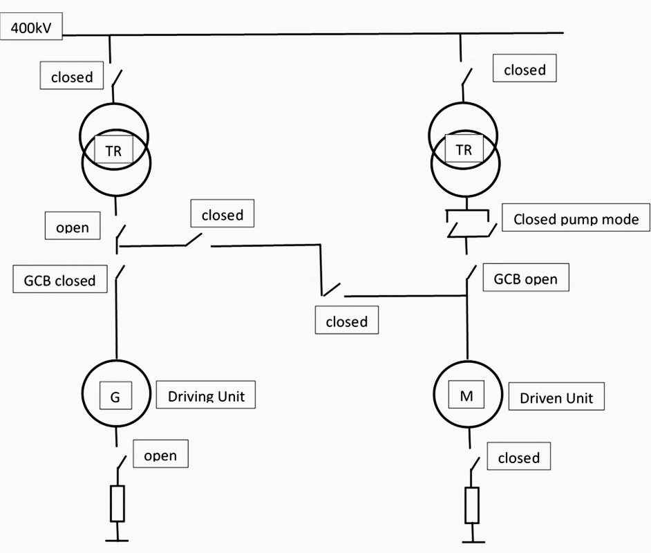
- Back to back acceleration is used when the SFC is not available. Here one of the machines is accelerated with excitation using the hydro turbine. It provides electrical power with an increasing frequency to accelerate another machine as a synchronous motor. Fig.1 shows a typical layout of SFC & back-to-back operation sequences.


The latter methods are now common practice as the stress on equipment is highly reduced compared to direct energizing thus increases the life time of the generator.
However during the frequency ramp up process, if a fault occurs, the fault current will have low frequency characteristics with values of low frequency typically below 47-48 Hz. Fault protection against such currents is hardly achievable since very little protective equipment can operate at such low frequencies.
The GCB is one of those protective devices whose low-frequency operation capability would be beneficial in case electrical fault occurs during launching sequence.
In addition, the PSPPs are those power plants which are switched on and off frequently depending upon the structure of the network and the energy demand on it.
There are some cases where the switching operations can go up to 10 times per day and these switching operations can be done with up to 50-60% of rated current of the generator. Thus, in addition to the ability of switching low frequency fault currents, the circuit breaker should also be able to have high electrical switching operations.
Off all the existing technologies for generator protection, only Vacuum Generator Circuit Breakers (VGCBs) have the ability to switch the fault currents at low frequencies as low as up to 15 Hz and their interrupting chamber can handle full load currents for as high as 10,000 electrical switching operations.
Power plant reliability is a major concern for energy suppliers. In order to produce energy safely and efficiently the installed equipment must protect the plant equipment in all possible scenarios in order to ensure high availability of the plant. Unplanned power plant outages can cause revenue loss and incur repair costs.
VGCBs are one of the best solutions for protecting energy generation assets. They protect the network components in case of short circuit currents which are more stress full than traditional circuit breakers.
Over the last decades Vacuum Circuit Breakers (VCB) are the most preferred switching devices in the medium voltage levels up to 52 kV. More than 80% of today’s new installation employs vacuum switching technology [4].
Special test parameters in terms of short circuit breaking and TRV withstanding capability were introduced by the standards IEEE C37.013 (1997) [5] & IEC/IEEE 62271-37.013 (2015) [6] to meet such high demands. Vacuum Generator Circuit Breakers (VGCBs) have successfully passed all mandatory tests and are fully qualified as Generator Circuit Breaker since the first introduction of the generator breaker standards in 1997.
Extensive developments were made in the field of vacuum physics to extend the range of the normal current carrying capability with natural cooling up to 12,500 A and the short-circuit breaking capability up to 100 kA.
Further investigations and developments are still on-going to push the VGCB’s potential further.
This article presents a case study about a fault scenario happened in a pumped storage plant during startup process and the damages occurred to the stator due to the fault. It is also explained how the extent of damage could have been reduced if the existing GCB had the ability to interrupt the low frequency fault current.
2. Case study
The scheme involved in this case study uses back to back launching mode. The PSPP is equipped with generators driven by Pelton turbine that are used as driving units and with motor generator connected to a pump turbine which are the driven units. Each of these units is rated 170MVA with stator voltage being 15.5kV. [2]
Since both stators are connected, the circuit is protected against earth fault with the driven unit relay; the driving unit star point is open.
As a matter of fact, a fault occurred during this launching sequence and the following protection was activated:
| 09:48:29.640 | Driving U | Stator earth fault |
| 09:48:00.600 | Driving U | Rotor earth fault |
| 09:47:58.960 | Driving U | Generator CO2 emission |
| 09:47:58.920 | Driving U | Field breaker open |
| 09:47:58.800 | Driving U | Grid breaker open |
| 09:47:58.640 | Driving U | Differential protection |
| 09:47:58.520 | Driving U | Excitation thyristor fuse melt |
| 09:47:58.480 | Driven U | Stator earth fault |

The inspection undertaken after the fault showed several damages on the driving unit stator and rotor, but no damage on the driven unit at all, even though the insulation resistance of the driven unit circuit was almost zero.
On the driven unit side, the stator winding was meggered on its own and showed high insulation resistance values; whereas the IPB duct meggering showed poor values. These IPB ducts being in a humid ambient, with some water dripping, the insulators had surface contamination.
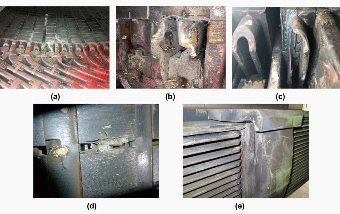

The fault was very likely triggered in the driving unit where a forgotten foreign object must have impacted the stator winding. A screw driver end was later found in the bottom of the generator end windings.
Simultaneously, the driven unit IPB had a very poor insulation resistance because of heavy moisture in the IPB gallery. The IPB insulation was found to be almost zero after the fault and back to several MΩ after 2 day drying.
Hence, as the first earth fault resulted in a voltage potential increase of the neutral side and a potential increase to phase to phase voltage of the phases, the latent IPB fault broke down resulting in a double earth fault on two different phase of the electrical circuit.
Let’s note that the damages were not as severe as a phase-to-phase fault with the generators connected to the grid since the short circuit power was in this case moderate.
On the MV breaker side, since the Generator Circuit Breaker (GCB) opening of the driving unit is inhibited during low frequency operation (f<47Hz) and the event occurred just below this threshold, the GCB was not triggered by the protection relays. As a consequence, the duration of the fault led to extensive damages found.
The almost instantaneous variation of stator current induced a very important voltage on the rotor side, which led to arcing between the 2 poles (input and output poles) and rotor body. The voltage surge was strong enough to damage inter turn insulation on one pole.
3. Application of Vacuum Generator Circuit Breaker
Today more than 80% of the switching devices installed in the medium voltages from 7.2kV up to 52kV are VCBs due to their many advantages over other existing technologies. Until the end of 90’s, it was not possible to utilize the potential of this long proven vacuum technology for the generator switching applications even though they fall under medium voltage applications.
The only suitable switching technology used for the generator applications was using SF6 as an arc quenching medium. But the technological developments in the field of vacuum arc physics enabled the vacuum circuit breakers to interrupt high short circuit currents up to 100kA and carry high rated currents up to 12500A.
The most commonly used contact types for vacuum generator circuit breakers are AMF (Axial Magnetic Field) contacts as shown in the Figure 4.
When the vacuum arc is created and the current is passed through the contacts, the higher amplitudes of the current make the arc constricted and due to the presence of axial magnetic field from the contact design the arc is forced to diffuse over the entire surface of the contact.
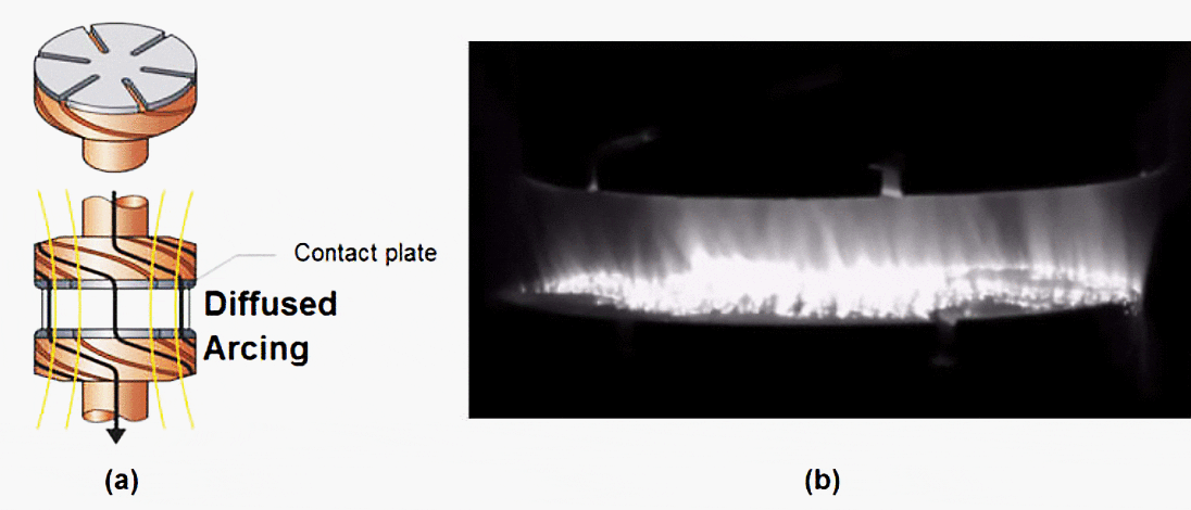

The arc voltage due the diffused arc between AMF contacts is considerably low but it does have a noticeable effect on the DC decaying behavior of short-circuit current in generator circuits, especially the generator-source current.
Recent measurements show that the arc voltage for AMF contact types (diffuse arc) is in the range of 80 – 120 V. The resistive character of an arc can reduce the DC time constant after the contact parting leading to a positive effect on the decaying of the DC offset and reduce the arcing time significantly.
Specific simulations were performed with 100 V of arc voltage and presented in references [9] [10].
This lead to a significantly high number of switching operations for VGCBs – both load current (maintenance-free up to 10,000 CO operations and more) and short-circuit current (>30 operations at full short-circuit current rating).
This makes VGCBs as ideal switching device for applications with very high amount of switching operations such as pump storage, where load current is switched very often.
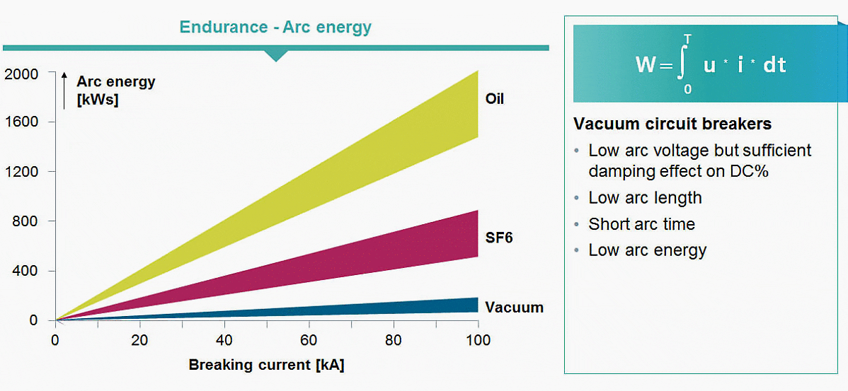


Also the low contact erosion and the diffused arc is the reason why the VGCBs can handle low frequency switching. The main challenge on GCBs while switching low frequency currents is the prolonged arcing times.
All our VGCBs are tested with arcing times of at-least 50 – 60 ms which guarantees their ability to switch low frequency currents without any issues. This is further supported by the extensive experience of VCBs installed in German railway networks where the operating frequency is 16.7 Hz.
In the following section the PSPP in the above case study is simulated using EMTP software PSS ® NETMOAC by taking into account the switching characteristics and breaking capability of a VGCB.
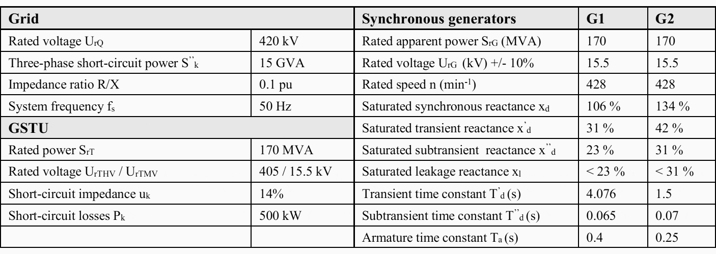

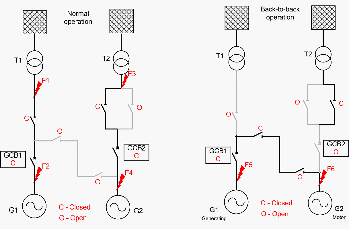
Various fault scenarios have been considered to calculate highest possible stresses in order to guarantee the reliability of the power plant as shown in Figure 7.
The following fault initiation conditions have been taken into account to simulate the highest stress possible on the GCBs installed at two generators:
- Fault currents are calculated for the scenarios F1 to F4 with both generators operating in normal operation mode and F5 and F6 that can happen during back-to-back operation.
- Short circuit cases in normal operation mode are calculated for both generators operating in no load, lagging & leading modes.
- Short circuit cases in back-to-back operation are calculated for G1 in generator mode and G2 in motor mode with currents of lower frequency nature i.e. 40 Hz and 25 Hz.
The contact separation shall take place at 45 ms after the short-circuit initiation with minimum time for protection relay of 10 ms and 35 ms mechanical opening time of the VGCB. Simulation results for both generator-source and systems-source fault currents are presented in Table 2.
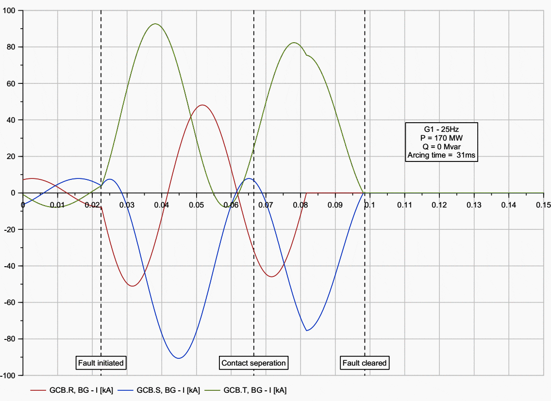
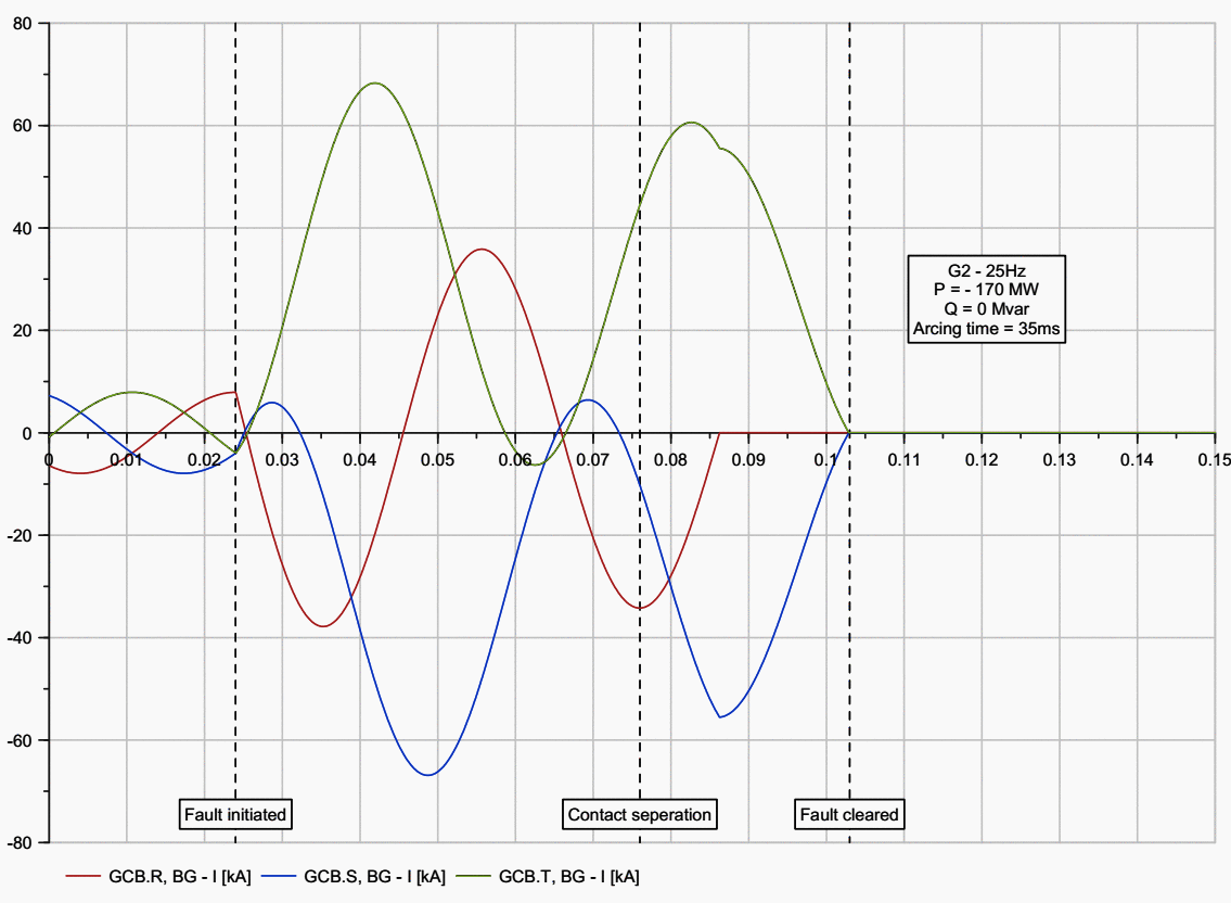
Due to space constraints the curves for only low frequency conditions are showed to provide an impression about long arcing times that are possible in such cases and why it is important to use a GCB that can able to handle long arcing times.
The resulting short circuit current values from Table 2 (see below) reflect the same.
The maximum possible arcing times that are resulted for these machines are when fault occurred during 25Hz operation which is a possible scenario during back-back operations. For both machines the arcing times are in the range of 35ms (Figure 8).
However, for typical PSPPs these arcing times can go up to 60ms depending upon the machine parameters and the GCBs must be able to handle such long arcing times.


As explained before VGCBs due to their very low arc energy can handle such long arcing times without any issues and still able to provide high electrical switching operations.
On the other hand, the gas GCBs like SF6 type has very high arc energy and the arcing contact cannot withstand such long arcing times. This is one of the reasons why the installed breaker in the PSPP of our case study did not trip when the fault happened as the frequency is below its nominal frequency of 47 Hz and increased the extent of damage to the stator.
Thus VGCBs are in general considered to be an ideal solution when switching PSPPs due to their advantages in terms of switching characteristics as well as being maintenance free for high switching cycles.


4. Conclusion
Back-to-back starting method is one of the commonly used principles in PSPPs to ramp up the machines to pump mode. The GCBs which are installed to increase the availability and thus the reliability of the power plant has to withstand the stresses while PSPPs that are more demanding than conventional power plants.
High electrical switching operations with 50-60% of load currents and being able to handle long arcing times if a fault occur during the back-to-back starting process due to the low frequency nature of the currents.
real time case study is presented here where a two phase to earth fault occurred in a machine in generating mode while ramping up the other machine in motor mode.
While assessing the damage to affected stator, it is realised that the extent of this damage could have been reduced if the installed circuit breaker had been tripped during the fault.
However due to the low frequency nature of the fault currents (< 47Hz) and the installed GCBs being not suitable to interrupt such currents the breaker had not received trip signal. This shows how important the breakers ability to interrupt low frequency currents in improving plants reliability and provides better protection to the plant assets.
VGCBs which use vacuum as an interrupting medium are the only switching technology that are suitable to interrupt such low frequency currents where the arcing times can last up to 60ms.
In addition to this, due to the low arc energy, the VGCBs offer up 10,000 times of electrical switching operations with full load current without any maintenance which is an another important requirement for PSPPs.
In this article, the affected PSPP from the case study is simulated using EMTP software called NETOMAC with VGCB switching characteristics where it is shown that the fault will be cleared within 80ms that would reduce the extent of damage on the stator.


With many advantages like high switching operations, very minimal maintenance, low arc energy and being environmental friendly due to absence of SF6 gas, VGCBs bring an added value to the power plant industries and especially PSPPs in protecting various assets and reducing the maintenance costs.
Thus the availability and the reliability of the plants will be in a better position with installing VGCBs for the protection of the power plant generator and the respective step up transformer.
Which challenges are you facing in pump storage power plants?
This video is a customer interview with the challenges customers experience in pump storage applications.
What are the benefits of vacuum generator circuit-breaker in pump storage?
This video is a customer interview with the benefits in pump storage power plants from our customers’point of view.
References
- D. Merwe, “Protection at a pumped storage station uses static frequency starting” Power
system protection conference, Johannesburg, 2012. - J.L. Drommi, “Double earth fault in a pumped-storage plant during back to back launching sequence”, IRMC 2017, Paris
- “Challenges and Opportunities For New Pumped Storage Development” – A White Paper by NHA’s Pumped Storage Development Council
- CIGRE Technical brochures “The impact of the application of vacuum Switchgear at Transmission Voltages”, WG A3.27, July 2014 (ISBN: 978-2-85873-287-6)
- IEEE Std C37.013-1997, “IEEE Standard for AC High-Voltage Generator Circuit Breakers Rated on a Symmetrical Current Basis”, March 1997
- IEC/IEEE 62271-37-013, “High-voltage switchgear and control gear – Part 37-013: Alternating-current generator circuit-breakers”, Edition 1.0, 2015-10
- B. Kulicke, H. H. Schramm, “Application of Vacuum Circuit-Breaker to Clear Faults with Delayed Current Zeros”, IEEE Trans. Power Delivery, vol.3, no.4, Oct.1988, pp.1714-1723
- K. R. Venna, H. Urbanek, N. Anger, “Difference between Switching Of Motors & Generators with Vacuum Technology”, Paper 0872, CIRED 2017
- H. Urbanek, K. R. Venna, N. Anger, “Vacuum Circuit Breakers – Promising Switching Technology for PSPP up to 450 MVA”, ICEPE-ST, Xi’an – China 2017
- K. R. Venna, N. Anger, T. Kleinert, “Role of vacuum generator circuit breaker in improving the plant efficiency & protecting the generators up to 450 MVA”, Power Gen- EU, 2016


any steps of switching operations ?
Thanks for Sharing the case study. Ref fig 8 A , R phase current seems to have been interrupted before current zero, which may lead to voltage stress on the stator winding. Both S and T phase currents , almost in opposite phase, may produce the magnetic field interfering with the arcs in individual phase interrupter of S and T phase.
We had a good experience with SF6 breaker with SFC starting , being solo unit of 150 Mw
Maintaining the driving rod (external to the interrupter) in dry condition is essential to avoid external flashover… ( unlike , SF6 breakers)
Very good article
Good explanation and new technical papers which enhance our knowledge and experience.