Protection schemes
It is difficult to define precisely the protection schemes that should be adopted for an electricity distribution system, given the large number of valid alternatives for each situation, but some schemes will be presented as a guide for protecting the various elements that make up a power system.

However, any protection scheme should strike a balance between the technical and economic aspects so that, for example, sophisticated protection devices are not used for small machines or for less important power system elements.
Ok, this is the list of generators and motors we’ll observe here.
1. Generator protection
Generator protection should take into account the importance of the generator and its technical characteristics such as power, voltage and earthing arrangement, plus any economic considerations. A complex protection scheme can ensure that the generator is protected against whatever faults may occur.
It is, therefore, necessary to define a protection scheme that is adequate for the size of the machine. Two generator protection schemes are given below, based on suggestions by manufacturing companies.
Go back to protection schemes ↑
1.1 Small generators


For small generators, typically up to 5 MVA, it is considered necessary to have:
- Protection against internal faults;
- Back-up protection for external faults using overcurrent relays with voltage restraint;
- Reverse-power protection;
- Earth-fault protection, using an overcurrent relay;
- Protection against overloads by means of thermal relays.
This scheme is illustrated in Figure 1 (for relay identification, see article ANSI codes).


Go back to protection schemes ↑
Large generators


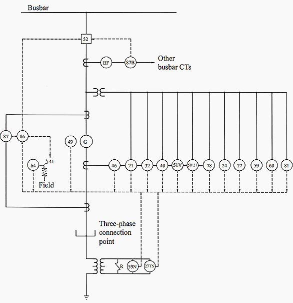
For large generators, say over 5 MVA, the protection, which is shown in Figure 2, should normally comprise:
- Differential protection to cover internal faults;
- Earth-fault protection using high impedance relays;
- Back-up protection by means of distance or overcurrent protection with voltage restraint;
- Reverse-power protection;
- Negative-phase sequence protection;
- Protection against loss of excitation;
- Protection against overload using thermal relays.


Go back to protection schemes ↑
Generator protection (VIDEO SESSION)
2. Motor protection
The amount of protection and its type, used for a motor is a compromise between factors such as the importance of the motor, the potential dangers, the type of duty and the requirements of protection coordination against the cost of the protection scheme.
- Protection of low power motors (less than 100 HP);
- Protection of motors up to 1 000 HP;
- Protection of motors greater than 1 000 HP;
- Additional protection for synchronous motors.
In protection schemes, the starting equipment of the respective motors has not been represented.
Go back to protection schemes ↑
2.1 Protection of low power motors
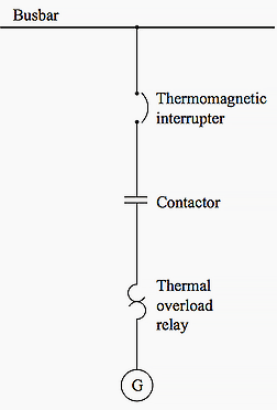
Low power motors are normally protected by fuses associated with thermal overload relays incorporating bimetallic elements (Figure 3) – the fuses protecting against short circuits.


Or low voltage breakers plus thermal overload relays (Figure 4) when the breaker should have a magnetic element to trip instantaneously under short circuit conditions.


Go back to protection schemes ↑
2.2 Protection of motors up to 1 000 HP
The protection arrangements should include thermal protection against overloads and short-circuits (49/50), protection for locked rotor (51) and earth-fault protection (50G), as indicated in Figure 5 below.


Go back to protection schemes ↑
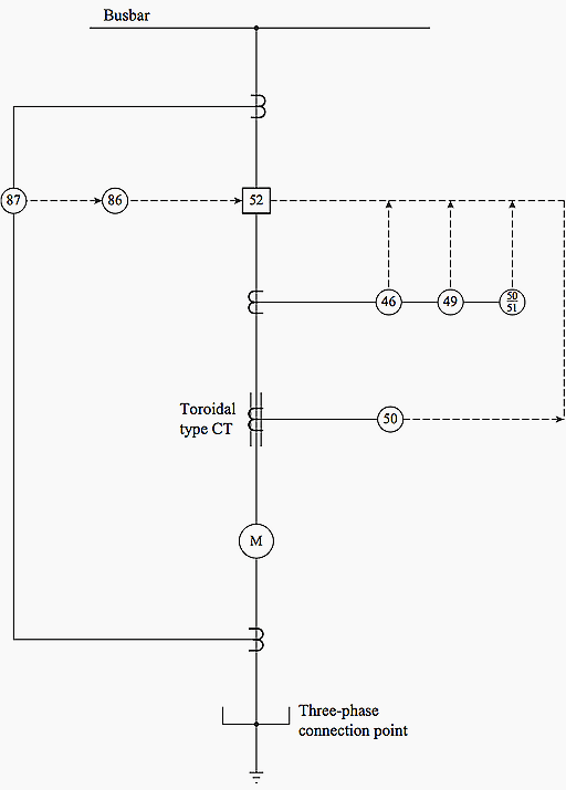
2.3 Protection of motors greater than 1 000 HP
Protection scheme shown in Figure 6 includes unbalance protection (46), thermal protection against overloads (49), protection for a locked-rotor situation (51), differential protection for internal faults (87), back-up for short-circuits (50) and earth-fault protection (50G).


Go back to protection schemes ↑
2.4 Additional protection for synchronous motors over 1 000 HP
In addition to the protective devices indicated in Figures 4 and 5, a large synchronous motor requires protection for the field winding, plus a low power factor relay (55) and undervoltage protection (27), and a high/low frequency relay (81) to prevent the motors running under conditions of low frequency operation.
The schematic diagram for the protection of synchronous motors over 1 000 HP is given in Figure 7.


Go back to protection schemes ↑
2.5 Protection for the field winding
This would require an earth-fault protection relay (64) and a field relay (40) to deal with loss of excitation current.
Go back to protection schemes ↑
Motors protection (VIDEO SESSIONS)
Reference // Protection of Electricity Distribution Networks by Juan M. Gers and Edward J. Holmes (Purchase paperback from Amazon)


Good day
Please reply to this email so that I could attach a full detail of the product I need.
Thank you.
– Generator Protection Device
Kind regards.
Neo
Me interesa mucho estos temas Gracias
Differential Inter Turn Protection
Thank you,,,,, for the articles,,,,
You present lectures in a very effective, easy to understand methodical / systematic.
Thank you, great man !!