
Estimated Study Time: 20 minutes
Generators Protection Study
The protection system for MV generators (synchronous machines) must be carefully selected and studied for the application it is destined for and it is not normally possible to define a single solution.
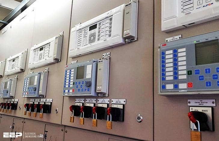 Protections For Medium Voltage Synchronous Machines (Generators) - photo credit: Kirby Automation Limited
Protections for synchronous machines (generators)
Only medium voltage generators are analysed and large machines (above 100 MVA), where selection of the protection system is necessarily made also according to the interface towards the transmission system, are excluded from this description.
The philosophy of protection relays is developed on the basis of knowledge that faults in generators can be divided into two main categories:
- Abnormal operations and working conditions, such as:
- Overload;
- Over speed or under speed;
- Overvoltage and undervoltage;
- Unbalanced loads;
- Excitation faults (field circuit or voltage regulator);
- Prime motor faults (or of the speed regulator).
- Insulation faults, such as:
- Ground faults (including rotor faults);
- Phase-phase and three-phase faults;
- Faults between the turns of the same phase.
The setting value of the protection must be calculated above the transient current, voltage and frequency values and the trip time must be such as to allow re-establishment of the electrical parameters to within the range of normal operating values.
Protection subgroups
The protections of a synchronous machine can then be divided into the following main sub-groups:
1. Main protections or zone protections
Operation – These are the protection functions which must operate instantaneously for faults which occur inside the relative zone and must remain stable for external faults (through faults).
2. Back-up protections
Operation – These are the protection functions which must operate for faults which occur on the load side of their connection point. These protection functions must have an intentional delay to allow a selective trip so as to only operate in the faulty zone.
3. Protections for abnormal operating and service conditions
Operation – These are the protection functions which must operate or prepare an alarm for any abnormal condition which may occur during running. The anomalies are detected by measuring appropriate electric parameters.
Protection functions for generator protection
Depending on the rated power of the machine and on the type of application, all or some of the following protection functions can be used to protect the generator.
Each function carry its designation code described below (click code to jump to more detailed description):
| IEEE C37-2 Code | Description |
| relay 87 | Differential protection generator (sometimes also called 87G) |
| relay 49 | Stator overload thermal protection |
| relay 51 | Overcurrent protection |
| relay 40 | Excitation fault protection (loss of field) |
| relay 32 | Reverse power protection (return energy) |
| relay 46 | Negative sequence overcurrent protection |
| relay 21 | Under-impedance protection (as an alternative to overcurrent protection for voltage control when a unit transformer exists) |
| relay 50V | Overcurrent protection with voltage control (as an alternative to protection against under-impedance when there is no unit transformer) |
| relay 27 | Undervoltage protection |
| relay 59 | Overvoltage protection |
| relay 81 | Over and underfrequency protection |
| relay 24 | Overflux protection |
| relay 64R | Rotor ground protection |
| relay 64S | Stator ground protection (a function of the type of neutral status) |
Other protection functions exist which are used for alternator protection such as:
| ANSI Code | Description | ANSI Code | Description |
| 5 | Accidental energization | 60 | Voltage balance relay |
| 37 | Underpower relay | 78 | Out of step relay |
| 49R (51R) | Rotor overload |

‘87G’ Differential protection
The main stator winding protection is entrusted to a differential relay with restraint characteristic. This relay compares the current values at the terminals of each phase of the winding and trips when the differential exceeds the relay setting value. It also ensures protection against phase-phase faults inside the stator winding.
Use of the differential protection can allow identification of ground faults inside of the protected zone as well, but its sen- sitivity is limited by the value of the ground fault current.
‘49’ Thermal protection against stator overload
All overloads cause abnormal heating conditions of the stator winding which must be eliminated before the temperature reaches dangerous values for the machine.
The protections also take into account the thermal condition of the machine before the overload occurs.
‘51’ Overcurrent protection
This protection function is not strictly necessary for alternators since operation under overload also requires the turbine to be able to deliver more power or for the excitation system to be able to increase the field in the machine above the rated value.
These conditions are rather difficult to produce and consequently this protection generally operates for external faults and for this reason must be delayed to prevent false trips.
‘40’ Protection against excitation faults (loss of field)
The protection against loss of excitation is entrusted to relay 40 which controls the excitation state at the stator terminals. In practice, this relay measures the current which changes from ‘capacitive’ to ‘inductive’ as a consequence of lack of excitation.
When there is loss of excitation, the generator behaves like an asynchronous generator which absorbs reactive power from the network and its impedance is consequently of inductive type (under-excitation of the capacity curve). The setting of the protection must be calculated not to cause unwanted trips in transient conditions, such as putting the machine in parallel with other sources.
It is obvious that the protection only operates when the generator operates in parallel with other sources (or power factor correction banks).
‘32’ Protection against reverse power (return of energy)
When the power source which moves the turbine fails, the generator (with the turbine always connected to the axle) operates like a motor and the active power necessary to keep the machine rotating is taken from the network.
The minimum drawing power required of the network by a coupled generator is a function of the type of turbine and can vary between less than 1% (steam turbine) up to very high values for generators coupled to diesel motors.
As for protection against loss of field, it is obvious that the protection only operates when the generator operates in parallel with other sources.
‘46’ overcurrent protection against negative sequence
Balanced three-phase loads produce a field reaction in the stator which rotates in synchronism with the rotor. When there are unbalanced loads, the negative sequence component in the stator current induces a current in the rotor with double the rated frequency. This current which flows through the rotor winding causes serious heat rises in the rotor.
Unbalanced load conditions can be imposed by the network outside the generator, for example by:
- Single-phase loads;
- Different impedances between the phases (e.g.: different phase terminal tightening);
- Open circuit on a transmission line;
- Lack of transposition between the phases;
- Faults between the turns;
- Fault at a circuit-breaker pole on closing;
- Trip of only one phase of a fuse bank;
- Prolonged unbalanced operation, such as phase-phase
- Fault or phase to ground fault; negative sequence harmonics.
The protection settings must be calculated so that the time-current trip characteristic is as close as possible to the thermal tolerability curve of the generator and at the permanent limit of tolerability for unbalanced load.
‘21’ under-impedance protection
This protection is necessary to identify the faults outside the machine and take the generator out of service in the case where they are not eliminated by their own protections. This protection is generally applied to generators with unit trans- former.
The protection measures the impedance (ratio V/I) and trips when this is lower than the set values. A relay with circular characteristic with centre in the origin of the R-X plane is generally used for alternator protection.
‘50V’ overcurrent protection with voltage control
This protection is similar to the under-impedance protection (in some models it measures the V/I ratio) and serves to identify faults outside the generator. The overcurrent threshold varies according to the voltage value (of latching). The more the network voltage is lowered the lower the current trip threshold is.
Generally, the voltage latching characteristic recommends use of this relay to identify faults when, for any reason, the generator operates without the automatic voltage regulator.
Since this is a back-up protection, it must be coordinated with the other network protections to guarantee selective tripping.
‘27’ undervoltage protection
This function protects the generator and the users against excessive voltage drops which can occur when large users are started, when the voltage regulator does not work correctly or when there is a voltage drop due to fault not identified by other protections.
This relay must be regulated at the minimum value allowed for network operation and with a delay time which allows re-establishment of the transient voltage values originated by these phenomena. The delay time must take the response times of the voltage regulator and excitation circuit into consideration.
‘59’ overvoltage protection
This function protects generators and users against overvoltages which can occur due to sudden disconnection of the loads or due to a malfunction of the voltage regulator.
Generally, the protection is provided with two trip thresholds since it must be extremely rapid for large overvoltages which can cause insulation faults, whereas it must have long times for small overvoltages which can be solved by the voltage regulator.
‘81’ Over-frequency and under-frequency protection
The over- and under- frequency relay is used to identify variations in frequency generated by load fluctuations or bad operation of the speed regulator of the prime motor.
The threshold setting must be calculated at a frequency level equivalent to the maximum/minimum speed tolerated by the turbine and generator with continuity or for short periods (regulation is possible using several frequency thresholds).
‘24’ Overflux protection
This protection function measures the voltage/frequency ratio (V/f) and allows monitoring so that the magnetic circuit does not go into saturation. The result of an overflow condition is heating of the machine with consequent reduction in life, therefore the characteristic normally used is of thermal type (with inverse time).
Attention must be paid to the setting since at rated frequency, this protection operates exactly like an overvoltage protection with which it must therefore be coordinated.
‘64R’ protection against rotor ground fault
The field circuit of an alternator is generally isolated from ground. Therefore in the presence of an initial ground fault it is not necessary to stop the generator and just an alarm is possible.
To be able to monitor the field circuit, it must be possible to overlay a low frequency signal (typically about 20 Hz) on the direct current circuit which, when suitably monitored, allows the level of machine insulation to be shown.
The protection is therefore associated with a generator at low frequency to form a single measuring system.
‘64S’ protection against stator ground fault
Identification of ground faults in a generator is a function of the way in which the neutral is run. In medium voltage generators there are practically only two types:
- Isolated neutral;
- Neutral grounded by a resistance and fault current value generally a few Amperes (typically 5-10 A).
For networks with isolated neutral: A homopolar overvoltage protection must be provided which is the only one to ensure a definite identification of the fault.
Associated with this protection (if there is a minimum of capacitive current in the network) is directional homopolar overcurrent protections are installed which only and exclusively operate for faults inside the machine, allowing selective identification of the fault.
For networks with neutral grounded: by means of resistance (typically on the star point of the alternator), it is necessary to provide:
- a protection on the grounding (either voltage or current) and, furthermore, in the case where there are several grounding in the network at the same voltage level (metallically interconnected networks),
- a directional ground overcurrent protection on the line side (MV compartment) as well, with trip direction from the network towards the generator.
The directional overcurrent protection (67G) only identifies ground faults in the generator and is therefore the first step in selectivity also being able to turn out very rapid.
On the other hand, the protection on the grounding (star point) (51G) identifies faults in any point of the network and therefore represents the last step of selectivity and must be delayed.
Protection trip matrix
It is not sufficient to provide protections to guarantee safety and a high level of service continuity in the plant, but it must also be ensured that the protections operate and act on the most appropriate operating parts.
The single line diagram and table are the example of a generator riser where the protection functions provided are detailed and the example of a possible trip matrix is given, with indications as to the possible actions that the various protection functions must carry out.


Example Generator Protection In Hydropower Plant
ABB’s injection-based 100% stator and rotor earth-fault protection with generator protection type REG670.
Generator Protection Fundamentals (VIDEO)
Reference // Protection criteria for medium voltage networks by ABB
Related electrical guides & articles


Edvard Csanyi
Hi, I'm an electrical engineer, programmer and founder of EEP - Electrical Engineering Portal. I worked twelve years at Schneider Electric in the position of technical support for low- and medium-voltage projects and the design of busbar trunking systems.I'm highly specialized in the design of LV/MV switchgear and low-voltage, high-power busbar trunking (<6300A) in substations, commercial buildings and industry facilities. I'm also a professional in AutoCAD programming.
Profile: Edvard Csanyi

hello dud …..let me ask you one question ………….in MTU GENERATOR ALL THE TIME THE ALARM IN THE GENERATOR IS OVERVOLTAGE PLS WHAT I WOULD TO MAKE ….
Mr. Csanyi,
I would like to thank you very much for the Nobel work you do for the electrical engineering community all over the world. Hopefully, one day I would have to express to you personally my gratitude.
Adrian Cocoli
Hi Edvard,
Greetings of the day. This information on MV Generator Protection dated 4th Dec.2017 which I received in my mail today ( 23rd March 2019 ) only, is quite informative and it is of great help both to new & experienced protection engineers. Keep up the good work, my friend.
Hello Edvard,
I’m Jignesh Patel from India. Completed Electrical Engineering in the year 1994. Now leading the business Parth Electircals & Engineering Pvt Ltd. In India.
I have been reading your Articles on EEP portal on MV, LV power system and protection philosophy and different type of protection relating scheme a d many more
I have one question about the use of Current Transformers and Potential Transformers, we are still depend on the age old technology of having wound type Cast Resin CTs. These are susceptible to failures due to PD generated within the cast resin due to temperature and also surface discharges due to atmospheric effect.
If we can completely replace these cast resin CTs or PTe then the MV Switchgear can be very reliable and almost maintenance free.
I know optical CTs are making inroads, however the cost effectiveness and reliability is still an issue for MV Switchgear panels.
Have you ever came across this question and though of any solution to this.
Pls share your ideas on this.
Best regards
Jignesh Patel
Hi
i reading almost every article you sending , its helping me a lot .
i know you very busy , if you can send me you email i wish to send you some specific question ,
many tanks
Yosi