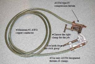
Each region shall implement procedures to ensure the adequacy of protective grounds and shall periodically review grounding practices at each facility to determine the proper size, length, and number (if parallel grounds are required) of protective grounds.
Regions shall maintain and periodically update a listing of the maximum fault currents at each facility or location where Reclamation employees apply protective grounds.
These reviews should be conducted at 5-year intervals1 or sooner if change in equipment or system conditions call for specific revision.
Requirements
Protective ground cables and associated grounding equipment shall meet the following requirements:
1
Capable of conducting the maximum fault current which could occur at the grounded worksite if the de-energized line or equipment becomes energized from any source and for the fault clearing times.
A ground or jumper which is sized to conduct maximum available fault current should be adequate to safely conduct currents from other sources of hazardous energy, including steady-state currents induced by electromagnetic coupling from nearby energized lines or equipment.
2
Capable of carrying the maximum available fault current, including dc offset current due to waveform asymmetry for high values of fault circuit impedance X/R ratio. Refer to Section 5 for cable ampacity information and Section 6 for conductor sizing procedure.
3
Capable of withstanding a second energization within 30 cycles after a first inadvertent energization.
4
Applied at the worksite in a manner that the worker exposure or body contact voltage does not exceed the values given in paragraph 4.1 while the ground cables are conducting fault current. Refer to Section 6 for procedure to determine worker exposure voltage.
5
Connected directly to the equipment, bus, or conductor to be grounded. No impedance or device (circuit breaker, disconnect switch, transformer, line trap, etc.) shall be permitted in series between the point of connection of the protective grounds and location of contact by the workers.
6
Be easy to apply, satisfy the requirements of field application conditions, utilize minimum time and preparation for installation, and cover a wide range of usefulness. Standardization, to the extent practical, is desirable at each location to keep the number of sizes and types to a minimum.
7
Fabricated as an assembly of suitably rated components (conductor, ferrules, clamps) to withstand thermal and electro-mechanical stresses imposed while conducting fault current (Section 5).
8
Stored and transported properly to avoid damage and maintained in good working order (Section 10).
9
Equipment and line terminal ground switches shall not be substituted for personal protective grounds. However, ground switches may be closed in parallel with protective grounds to reduce fault current through the ground cables and lower the worker exposure voltage at the worksite.
Ground cables must be sized for the maximum available fault current, without benefit of any reduction in current due to closed ground switches.
10
Temporary removal of protective grounds for testing de-energized equipment not permitted. Rather, protective grounds shall be installed in a manner that allows de-energized equipment under test to be safely isolated from protective grounded circuit(s) for the duration of the test.
The method of double-isolation grounding provides an effective means of isolating equipment for testing.


