Few words about shunt capacitor banks
Shunt capacitor banks are mainly installed to provide capacitive reactive compensation – power factor correction. The use of SCBs has increased because they are relatively inexpensive, easy and quick to install and can be deployed virtually anywhere in the network.

Its installation has other beneficial effects on the system such is: improvement of the voltage at the load, better voltage regulation (if they were adequately designed), reduction of losses and reduction or postponement of investments in transmission.
Capacitor unit

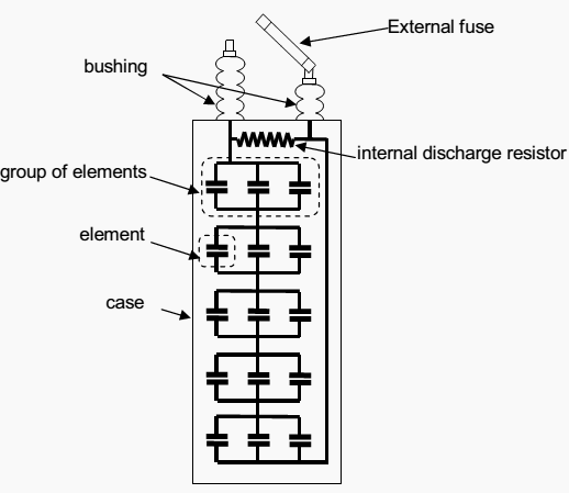
The capacitor unit is the building block of a shunt capacitor bank. The capacitor unit is made up of individual capacitor elements, arranged in parallel/series connected groups within a steel enclosure. Each capacitor unit is provided with a discharge resistor that reduces the unit residual voltage to 50V in 5 minutes.
Capacitor units are available in variable voltages and sizes.
The IEEE Std 18-1992 and Std 1036-1992 specify the standard ratings of the capacitors designed for shunt connection to ac systems and also provide application guidelines.
These standards stipulate that:
- Capacitor units should be capable of continuous operation up to 110% of rated terminal rms voltage and a crest voltage not exceeding 1.2 x √2 of rated rms voltage, including harmonics but excluding transients. The capacitor should also be able to carry 135% of nominal current.
- Capacitors units should not give less than 100% nor more than 115% of rated reactive power at rated sinusoidal voltage and frequency.
- Capacitor units should be suitable for continuous operation at up to 135%of rated reactive power caused by the combined effects of:
- Voltage in excess of the nameplate rating at fundamental frequency, but not over 110% of rated rms voltage.
- Harmonic voltages superimposed on the fundamental frequency.
- Reactive power manufacturing tolerance of up to 115% of rated reactive power.
Capacitor bank configuration
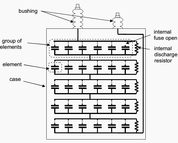
The use of fuses for protecting the capacitor units and its location (inside the capacitor unit on each element or outside the unit) is an important subject in the design of capacitor banks. They also affect the failure mode of the capacitor unit and influence the design of the bank protection.
- Externally fused capacitor unit/bank
- Internally fused capacitor unit/bank
- Fuse-less shunt capacitor banks
1. Externally Fused Capacitor Unit/Bank
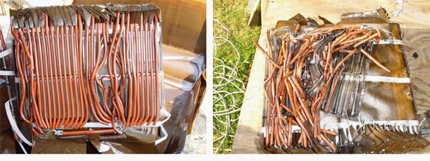
An individual fuse, externally mounted between the capacitor unit and the capacitor bank fuse bus, typically protects each capacitor unit. A failure of a capacitor element welds the foils together and short circuits the other capacitor elements connected in parallel in the same group.

The remaining capacitor elements in the unit remain in service with a higher voltage across them than before the failure and an increased capacitor unit current. If a second element fails the process repeats itself resulting in an even higher voltage for the remaining elements.
Successive failures within the same unit will make the fuse to operate, disconnecting the capacitor unit and indicating the failed one.
However, the kiloVAr rating of the individual capacitor unit may need to be smaller because a minimum of parallel units are required to allow the bank to remain in service with one fuse or unit out.
2. Internally Fused Capacitor Unit/Bank
Each capacitor element is fused inside the capacitor unit. The fuse is a simple piece of wire enough to limit the current and encapsulated in a wrapper able to withstand the heat produced by the arc. Upon a capacitor element failure, the fuse removes the affected element only.

The other elements, connected in parallel in the same group, remain in service but with a slightly higher voltage across them.
3. Fuse-less Shunt Capacitor Banks
The capacitor units for fuse-less capacitor banks are identical to those for externally fused described above. To form a bank, capacitor units are connected in series strings between phase and neutral.

When the capacitor element fails it welds and the capacitor unit remains in service. The voltage across the failed capacitor element is then shared among all the remaining capacitor element groups in the series.
EXAMPLE //
For example, if there are 7 capacitor units in series and each unit has 10 element groups in series then there are a total of 70 element groups in series.
If one capacitor element fails, the element is shortened and the voltage on the remaining elements is 70/69 or about a 1.5% increase in the voltage. The capacitor bank continues in service; however successive failures of elements will lead to the removal of the bank.
Manufacturer’s experience is that for modern capacitor units all element failures result in strong gas-free welded short circuits on the elements.

References:
- Substation design / Application guide – V AYADURAI BSC, C.Eng, FIEE Engineering Expert
- Shunt Capacitor Bank Fundamentals and Protection – Gustavo Brunello, Dr. Bogdan Kasztenny and Craig Wester (GE Multilin, Canada)


how can calculate the capacitor current for the following,
system voltage 400v, and 100kvar.
capacitor 136kvar at 480v..is the current calculate on 136kvar and 480v or 100kvar at 400v.
and to calculate the contactor and breaker currents..is it depend to which current also.
if you can give me example.
note, our LV system voltage 400v, 50hz.
thanks,
The statement “If one capacitor element fails, the element is shortened and the voltage on the remaining elements is 70/69 or about a 1.5% increase in the voltage.” is wrong. The right answer is that if one capacitor element fails, the element is shortened and the voltage on the remaining elements is 7/6 or about a 16.7% increase in the voltage.
It’s a really good to hear about machinery topics in this website.
Required newsletter for latest update
good particle
i think these capacitors should be near the factory not in the power station to minimize losses in transmission line.
but i still think that shunt capacitor is a better choice than series one ,Although it is more expensive for the same reactive power , but placing it in the ground level ,failure causing only voltage reduction , gradual increase in the voltage and low current is all advantages in shunt capacitors.