
Estimated Study Time: 5 minutes
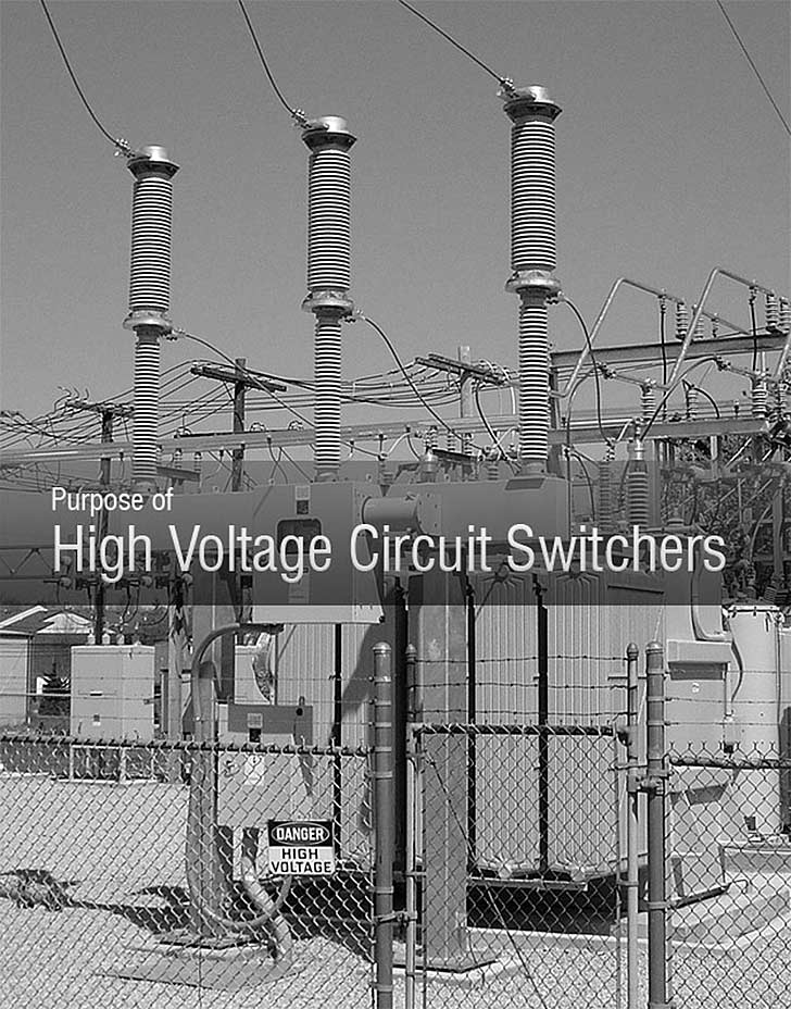
Three-phase Interruption and Protection
Circuit switchers have been developed to overcome some of the limitations of fusing for substation power transformers. Circuit switchers have SF6 gas interrupters and are designed to provide three-phase interruption (solving the unbalanced voltage considerations) and to provide protection for transient overvoltages and overloads at a competitive cost between the costs of power fuses and circuit breakers.
Additionally they can provide protection from power transformer faults based on differential, sudden pressure, and overcurrent relay schemes as well as critical operating constraints such as for low oil level, high oil or winding temperature, pressure relief device operation, etc.
Later models have been designed with improved interrupters that have reduced the number of gaps required for successful performance to a single gap per phase, thus eliminating the necessity of the disconnect switch blade in series with the interrupter.

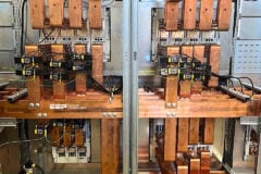
Circuit switchers are now available in vertical interrupter design (see Fig 2 – picture above) or horizontal interrupter design configurations with (see Figure 3) or without (see Figure 4) an integral disconnect switch.
The earliest circuit switchers had a 4 kA symmetrical primary fault current interrupting capability, but subsequent design improvements over the years have produced circuit switchers capable of 8, 10, 12, 16, 20, 25, 31.5, and 40 kA symmetrical primary fault current interrupting, with the highest of these interrupting values being on par with circuit breaker capabilities.

Horizontal interrupter line switchers provide load breaking, loop splitting, and line dropping capabilities for your most critical line switching applications. Additional applications include transformer magnetizing current interrupting and cable switching.
All circuit making and breaking operations are accomplished in SF6 gas, eliminating open air arcs.

Different model types, configurations, and vintages have different interrupting ratings and interrupting speeds.
Circuit switchers have been developed and furnished for applications involving protection of:
- Power transformers
- Lines,
- Cables
- Capacitor banks, and
- Line connected or tertiary connected shunt reactors.
Circuit switchers can also be employed in specialty applications such as series capacitor bypassing and for load= line =loop interrupting applications where fault-closing capabilit y is required (as fault-closing capability is not a feature inherent in disconnect switch mounted load =line =loop interrupters or in the disconnect switches these interrupters are mounted on).
Key Advantages
These are the main advantages of HV Circuit Switchers:
- Makes and breaks circuit in SF6
- Ships fully assembled to minimize installation time
- Local visual indication of gas pressure provided by color coded temperature compensated gas gauge
- Common gas system with gas density switch with low pressure alarm and low pressure lockout for remote status monitoring
- Compact design and easy installation makes this an ideal switcher for replacement of power fuses to achieve 3 phase protection
- Straight forward mechanical design insures long life, repeatable operation
Rated Duty Cycle
O – 0.3 sec – CO – 15 sec –CO
Resource: Electric Power Engineering Handbook – Leonard L. Grigsby (Get this book from Amazon)
Related electrical guides & articles


Edvard Csanyi
Hi, I'm an electrical engineer, programmer and founder of EEP - Electrical Engineering Portal. I worked twelve years at Schneider Electric in the position of technical support for low- and medium-voltage projects and the design of busbar trunking systems.I'm highly specialized in the design of LV/MV switchgear and low-voltage, high-power busbar trunking (<6300A) in substations, commercial buildings and industry facilities. I'm also a professional in AutoCAD programming.
Profile: Edvard Csanyi

Dear Edvard,
My name is Diego Melinc. I’m a General Manager of EMA Electromecanica S.A. the most important comany in Argentina manufacture of Circuit breaker of MV and HV, and we manufacture Primary and secundary Swichgear up to 38kV
I need contact to you to talk about more information about a HV circuit swicher for US market, can you send me your email to sendyou information?
Thank you very much
Thanks for the info , what is the min Voltage I can find the circuit switcher on the market ?
But how does an HV ckt. switcher has an edge over HV circuit breaker?