
Principle of operation and design
Miniature circuit breakers (MCB) are primarily designed to protect cables and lines against overload (thermal) and short-circuit (electromagnetic). They thus care for protecting this electrical equipment against excessive temperature rises and destruction in the event of a short-circuit.
They meet the requirements for different applications by various designs and with the aid of a comprehensive range of accessories (for example auxiliary and signal contacts etc.).
The structural shape of all line protection switches is similar. Certain dimensions are defined by the installation standards (in some cases national). The major differences lie in the widths (for example 12.5 and 17.5 mm) or depths (for example 68 and 92.5 mm).
The breaking capacity is one of the factors that determine the size.
Standards, tripping characteristics and rated switching capacity
MCB’s are subject to international and national norms. The design and test requirements are defined in the standard IEC 60898.
For the various applications three trip characteristics B, C and D are defined in IEC 60898 (Figure 1):

The tripping characteristics B, C and D under IEC 60898 are distinguished by the trip level of the short-circuit trigger
- Trip characteristic B is the standard characteristic for wall outlet circuits in domestic and utility buildings (I> ≥3 … 5*Ie)
- Trip characteristic C is advantageous when using electrical equipment with higher inrush currents as for example of lamps and motors (I> ≥5 … 10*Ie)
- Trip characteristic D is adapted to electrical equipment that can produce strong current surges such as transformers, electromagnetic valves or capacitors (I> ≥10 … 20*Ie)
In addition to the quality of releasing according to the tripping characteristic, a key feature of MCB’s is their rated switching capacity. They are assigned to switching capacity classes, which indicate the maximum size of short-circuit current that can be handled.
Standard values under IEC 60898 are 1500, 3000, 4500, 6000, 10000, 20000 and 25000 A.
When selecting a MCB to protect cables and conductors, the permissible let-through-I2·t values for conductors must be respected. They may not be exceeded during clearing a short-circuit.
Therefore the I2·t values in relation to the prospective short-circuit current are important characteristic of MCB’s.
In some countries, miniature circuit breakers are classified according to the permissible I2·t values. According to the “Technical Connection Conditions” (TAB) of the German power utilities (EVU) for example only MCB’s with a rated switching capacity of at least 6000 A and the energy limitation Class 3 may be used for selectivity reasons in distribution boards of domestic and utility buildings behind the meter.
For industrial applications a switching capacity of 10000 A (10 kA) is usually required.
Installation of Miniature Circuit Breakers, safety clearances
MCB’s as components of installation systems are usually designed so that compliance with safety clearance requirements is assured when arranged conform to the system structure.
Circuit breakers can cope with very high currents at high voltages when breaking short-circuits.

During the breaking process, the contact systems and arcing chambers consequently convert large amounts of power into heat energy.
In addition to high temperature rises of components such as contacts, de-ion plates and walls of the contact chambers, the energy converted into an arc results in heating of the air in the contact system to several thousand degrees Celsius and hence to the formation of a conductive plasma. This plasma is usually emitted through blow-out openings to the outside and must not reach any conductive parts to prevent secondary short-circuits.
For this season, safety clearances are specified for circuit breakers (Figure 2), within which no conductive parts – for example metallic walls or uninsulated conductors – may be located.
Frequently additional insulation components (phase partition walls or covers; in some cases optional) are used. With some products, additional insulation of the connected conductors is required in accordance with manufacturer specifications.
Non-compliance with the safety clearances can result in accidents with most severe consequences.
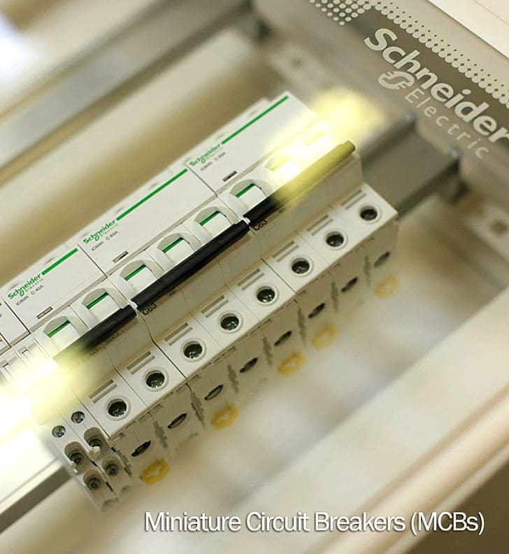
Example: Acti 9 MCB (VIDEO)
Resource: Allen Bradley – Low Voltage Switchgear and Controlgear


Very good
Dear Edward,it would be greatful if you briefly explained energy limitation class.
can I know why MCCB of say 63 A is preffered when a similar rating of 63A MCB is available .
thank you very much sir i learned a lot regarding mcb’s and some of doubts were clarified through u r article keep posting sir…..
sir plz post regarding MCCB’S AND CONTACTORS