
Estimated Study Time: 4 minutes
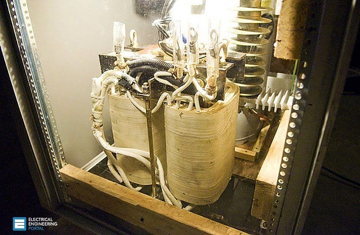
Two-winding transformer
A shielded transformer is a two-winding transformer, usually delta–star connected and serves the following purposes:
1. – Voltage transformation from the distribution voltage to the equipment’s utilization voltage.
2. – Converting a 3-wire input power to a 4-wire output thereby deriving a separate stable neutral for the power supply wiring going to sensitive equipment.
3. – Keeping third and its multiple harmonics away from sensitive equipment by allowing their free circulation in the delta winding.
4. – Softening of high-frequency noise from the input side by the natural inductance of the transformer, particularly true for higher frequency of noise for which the reactance becomes more as the frequency increases.
5. – Providing an electrostatic shield between the primary and the secondary windings thus avoiding transfer of surge/impulse voltages passing through inter-winding capacitance.

Figure 1 shows the principle involved in a shielded transformer. The construction of the transformer is such that the magnetic core forms the innermost layer, followed by the secondary winding, the electrostatic shield made of a conducting material (usually copper) and finally the primary winding.
Figure 2 shows this detail.
It can be seen that the high-frequency surge is conducted to ground through the capacitance between the primary winding (on the left) and the shield, which is connected to ground. Besides the shield, the magnetic core, the neutral of the secondary winding and the grounding wire from the electronic equipment are all terminated to a ground bar, which in turn, is connected to the power supply ground/building ground.

Figure 3 shows the proper way for an isolation transformer to be wired. Note that the AC power supply wiring and the secondary wiring from the transformer are taken through separate conduits.
Also, the common ground connection of the isolation transformer serves as the reference ground for the sensitive loads. The AC system ground electrode connection is taken through a separate metal conduit.

If these methods are not followed and wiring /earth connections are done incorrectly, noise problems may persist in spite of the isolation transformer.
Resource: Practical-Grounding-Bonding-Shielding-and-Surge-Protection – G. Vijayaraghavan
Related electrical guides & articles


Edvard Csanyi
Hi, I'm an electrical engineer, programmer and founder of EEP - Electrical Engineering Portal. I worked twelve years at Schneider Electric in the position of technical support for low- and medium-voltage projects and the design of busbar trunking systems.I'm highly specialized in the design of LV/MV switchgear and low-voltage, high-power busbar trunking (<6300A) in substations, commercial buildings and industry facilities. I'm also a professional in AutoCAD programming.
Profile: Edvard Csanyi

Hi
What would be an acceptable insulation resistance test value be for a shield be. ie the transformer we have lv megger is 8M Ohms with the shield grounded when we disconnect the shield from earth it is 123 G Ohms?
Please note that your winding is going to be at rated voltage when loaded and Shield will remain at Earth or zero potential, If LV megger is 8 Mohms with shield then thats actual and its very less, It can cause flash at later date.
Thanks for sharing..it is very informative.keep sharing.
hello , the existing equipment has 75 kva isolation transformer for 74 kva load ,for new system ,what size isolation transformer need for 85 kva load 480v/3p ?
also dose provide neutral for me, like totall 5 wire (-3P G,Neutral )
Dear Edvard Csanyi,
I always read your articles and the texts you provide in this site.
Thank you for all great information.
and my question is :
In a transformer with Dd0 connection we connect the earth screen directly to core clamp and through it to earth. is it true method?
Thank you again for information
Hi,
Does anybody knows how to test the power factor on this type of transformers with electrostatic shield?
Hi , kindly clarify—– In one of our plant having dry type isolation transformer 40 KVA, primary and secondary voltages are 415 V and pri. current is 32.1 A and sec. current is 55.6 as per Name plate data , kindly confirm is it possible in CURRENT Pr. 32A and Sec. 55.6 A even KVA and Volatges are same?
Hello,
My name is Michael Dawson and I will like to know whether you do carry the Isolation Transformers of the information below or any Transformers with the spec’s similar to that. If you do, I will like you to reply me back with the price of that so that I can proceed with the order.
Specifications:
Isolating Transformer: 7.5 KVA, 1 PH, 60 Hz
Primary: 208 VAC, 36 Amps
Secondary: 220/230/240 VAC, 63 Amps max
Open core and coil: 9 H x 9 W x 9 D
Thanks and hope to read from you soon.
Michael.
The information provided by you is really useful.
The servo stabilizers are known to be the best options for conferring protection to the electrnonic devices. Thus these devices are considered to be vital for enhancing the endurance of the devices. Servo Stabilizer Manufacturers, Isolation Transformer Manufacturers