Distribution system in general
Electric distribution system is all of that part of an electric power system between the bulk power source or sources and the consumers’ service switches. The bulk power sources are located in or near the load area to be served by the distribution system and may be either generating stations or power substations supplied over transmission lines.
Distribution systems can, in general, be divided into six parts, namely: subtransmission circuits, distribution substations, distribution or primary feeders, distribution transformers, secondary circuits or secondaries, and consumers’ service connections and meters or consumers’ services.
Figure 1 is a schematic diagram of a typical distribution system showing these parts.
The subtransmission circuits consist of underground cable, aerial cable, or overhead open-wire conductors carried on poles, or some combination of them. The subtransmission voltage is usually between 11kV and 33kV, inclusive.
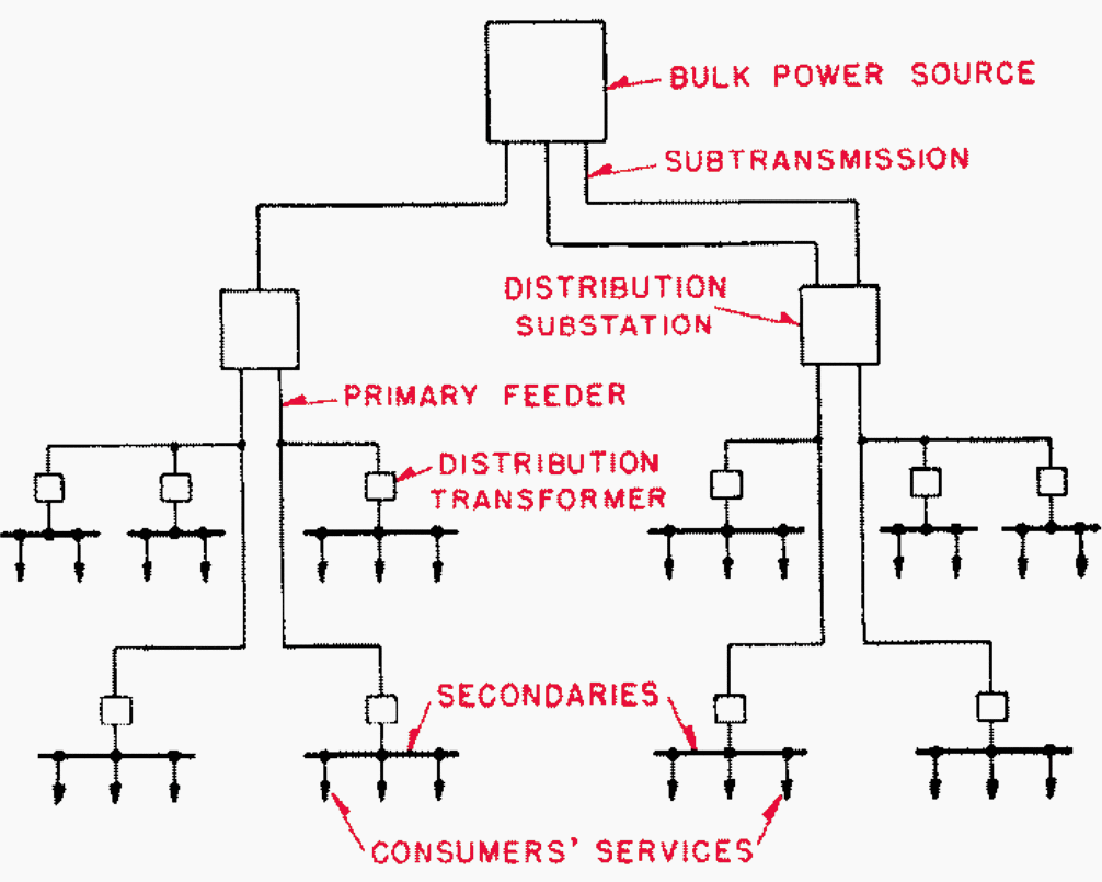

Each distribution substation normally serves its own load area, which is a subdivision of the area served by the distribution system. At the distribution substation the subtransmission voltage is reduced for general distribution throughout the area.
The substation consists of one or more power-transformer banks together with the necessary voltage regulating equipment, buses, and switchgear.
Now, let’s have a discussion about radial distribution networks and their characteristics, flexibility and layouts.
The Radial System
The radial type of distribution system, a simple form of which is shown in Figure 2, is the most common. It is used extensively to serve the light- and medium-density load areas where the primary and secondary circuits are usually carried overhead on poles.
The distribution substation or substations can be supplied from the bulk-power source over radial or loop subtransmission circuits or over a subtransmission grid or network.
The distribution transformers are connected to the primary feeders, subfeeders, and laterals, usually through fused cutouts, and supply the radial secondary circuits to which the consumers’ services are connected.
Oil circuit breakers arranged for overcurrent tripping are used to connect the radial-primary feeders to the low-voltage bus of their associated substation.
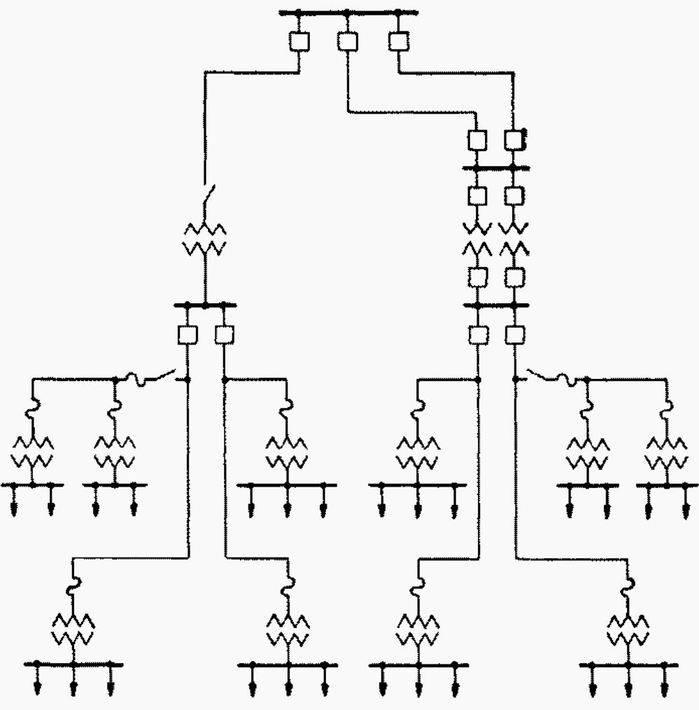

When a short-circuit occurs on a feeder its station breaker opens and interrupts the service to all consumers supplied by the feeder.
Manually-operated sectionalizing switches are often installed at the junction of the subfeeders and the main feeder.
The purpose of the fuses in the primary leads of the distribution transformers is to open the circuit in case of trouble in a transformer or on its associated secondary lines and prevent a possible shutdown of a considerable portion of the feeder or the entire feeder on such faults.
The subfeeders and laterals are sometimes fused to prevent tripping the feeder breaker at the substation and thus reduce the extent of the outage when a fault occurs on one of them.


Obviously, the transformer fuses, branch fuses, and feeder breaker should be properly coordinated so that the circuit will be opened at the proper point to keep the outage to a minimum. When a fault that is not self clearing develops on any section of the feeder, in one of its associated distribution transformers, or on one of its secondary circuits, a number of the consumers will be without service for a considerable period.
All consumers connected to the feeder will, of course, be affected if the fault is located so as to cause the feeder breaker at the substation to open.
The reclosing equipment provides one, two, or three reclosures before the breaker is locked open.
Fundamentally the advantages of the radial distribution system are simplicity and low first cost. These result from a straightforward circuit arrangement, where a sin-gle or radial path is provided from the distribution substation, and sometimes from the hulk power source, to the consumer.
With such a circuit arrangement the amount of switching equipment is small and the protective relaying is simple.
Frequently the system is radial only from the distribution substations to the distribution transformers. Because of the many system arrangements encountered it is sometimes difficult to determine in what major type a system should be classified.
To aid in such classification and to follow more readily the discussion of radial systems, it should be remembered that:
A radial system is a system having a single path over which current may flow for a part or all of the way from the distribution substation or substations to the primary of any distribution transformer.
Subtransmission
Power is transmitted from the bulk power source or sources to the distribution substations over the subtransmission circuits. These circuits may be simple radial circuits, parallel or loop circuits, or a number of interconnected circuits forming a subtransmission grid or network.
A radial arrangement of subtransmission circuits such as that shown in Figure 3 results in the lowest first cost.


This form of subtransmission is not usually employed because of the poor service reliability it provides. A fault on a radial subtransmission circuit results in a service interruption to all loads fed over it.
The economical use of subtransmission circuits and associated circuit breakers dictates that each subtransmission circuit carry a relatively large block of load.
An improved form of radial subtransmission is shown in Figure 4 below. Each radial subtransmission circuit serves as a normal feed to certain distribution substation transformers and as an emergency feed to others.
This arrangement permits quick restoration of service when a radial subtransmission circuit is faulted.


The substation transformers normally fed from the faulty circuit are each provided with an emergency circuit to which they can be switched either manually or automatically. This arrangement does not prevent an extensive service interruption for a short time and requires spare capacity to be built into the radial subtransmission circuits.
Because extensive service interruptions cannot often be tolerated, the subtransmission for a radial system usually takes the form of parallel or loop circuits or of a subtransmission grid.
Whether a loop or a grid arrangement of subtransmission circuits is preferable will depend largely on conditions in the particular load area, such as the load distribution, the topography, and the number and location of the bulk power sources.
A parallel- or loop-circuit subtransmission layout is shown in Figure 5, on which no single fault on any circuit will interrupt service to a distribution substation.


All circuits must be designed so that they will not be overloaded when any one circuit is out of service. Two parallel circuits are considered to be a sectionalized loop supplying one distribution substation.
However, two parallel circuits running over the same right-of-way are not nearly as reliable as two circuits following different routes. A fault on one circuit may involve the other if the two circuits arc closely adjacent. This is not as likely to result, however, with cable circuits as with open-wire circuits.
In other words, a ring is a loop from which substations can be supplied and into which power is fed at more than one point.
The ring arrangement is quite often used for subtransmission. It is a simple form of subtransmission network, and as the system grows it very often develops into a grid.
The network form of subtransmission is flexible in that it can readily be extended to supply additional distribution substations in the area it covers with a relatively small amount of new circuit construction. It requires a large number of circuit breakers, however, and is difficult and costly to relay.
The network or grid form of subtransmission shown in Figure 6 provides greater service reliability to the distribution substations than the radial and loop forms of subtransmission.


This is true particularly when the distribution system is supplied from two or more bulk power sources, because it is possible for power to flow from any bulk power source to any distribution substation.
This paralleling of bulk power sources through the subtransmission circuits also has the advantage of tending to equalize the load on the bulk power sources. In a large distribution system any two or even all of the above forms of subtransmission may be employed between the bulk power sources and the various distribution substations, depending upon the service requirement of the different substations and economic considerations.
The form of subtransmission employed is also influenced by the design of the distribution substations used.
Source: Distribution systems by John S. Parsons and H. G. Parnett (ABB)


