
Estimated Study Time: 14 minutes
For system protection 600V and below
The molded-case circuit breaker is the “workhorse” for system protection 600V and below. A circuit breaker is a device designed to open and close by nonautomatic means and to open the circuit automatically on a predetermined overcurrent without damage to itself when properly applied within its rating.
The following terms apply to molded-case circuit breakers:
Voltage – Circuit breakers are designed and marked with the maximum voltage at which they can be applied. Circuit breaker voltage ratings distinguish between delta-connected, 3-wire systems and wye-connected, 4-wire systems.
Breakers with slash ratings, such as 120/240 V or 480 Y/277 V, can be applied in a solidly-grounded circuit where the nominal voltage of any conductor to ground does not exceed the lower of the two values of the circuit breaker’s voltage rating and the nominal voltage between any two conductors does not exceed the higher value of the circuit breaker’s voltage rating.
Frequency – Molded-case circuit breakers are normally suitable for 50Hz or 60Hz. Some have DC ratings as well.
Continuous current or Rated current – This is the maximum current a circuit breaker can carry continuously at a given ambient temperature rating without tripping (typically 40˚C).
In accordance with NEC article 210.20 a circuit breaker (or any branch circuit overcurrent device) should not be loaded to over 80% of its continuous current unless the assembly, including the circuit breaker and enclosure, is listed for operation at 100% of its rating.
Poles – The number of poles is the number of ganged circuit breaker elements in a single housing. Circuit breakers are available with one, two, or three poles, and also four poles for certain applications.
Control voltage – The control voltage rating is the AC or DC voltage designated to be applied to control devices intended to open or close a circuit breaker. In most cases this only applies to accessories that are custom-ordered, such as motor operators.
Interrupting rating – This is the highest current at rated voltage that the circuit breaker is intended to interrupt under standard test conditions.
Short-time or Withstand Rating – This characterizes the circuit-breaker’s ability to withstand the effects of short-circuit current flow for a stated period. Molded-case circuit breakers typically do not have a withstand rating, although some newer-design breakers do.
Instantaneous override – A function of an electronic trip circuit breaker that causes the instantaneous function to operate above a given level of current if the instantaneous function characteristic has been disabled.
Current Limiting Circuit Breaker – This is a circuit breaker which does not employ a fusible element and, when operating in its current-limiting range, limits the let-through I2t to a value less than the I2t of a _-cycle wave of the symmetrical prospective current.
HID – This is a marking that indicates that a circuit breaker has passed additional endurance and temperature rise tests to assess its ability to be used as the regular switching device for high intensity discharge lighting. Per NEC 240.80 (D) a circuit breaker which is used as a switch in an HID lighting circuit must be marked as HID.
HID circuit breakers can also be used as switches in fluorescent lighting circuits.
SWD – This is a marking that indicates that a circuit breaker has passed additional endurance and temperature rise tests to assess its ability to be used as the regular switching device fluorescent lighting.
Per NEC 240.80 (D) a circuit breaker which is used as a switch in an HID lighting circuit must be marked as SWD or HID.
Frame – The term Frame is applied to a group of circuit breakers of similar configuration. Frame size is expressed in amperes and corresponds to the largest ampere rating available in that group.
Thermal-magnetic circuit breaker – This type of circuit breaker contains a thermal element to trip the circuit breaker for overloads and a faster magnetic instantaneous element to trip the circuit breaker for short circuits.
On many larger thermal-magnetic circuit breakers the instantaneous element is adjustable.
Electronic trip circuit breaker – An electronic circuit breaker contains a solid-state adjustable trip unit. These circuit breakers are extremely flexible in coordination with other devices.
Sensor – An electronic-trip circuit breaker’s sensor is usually an air-core current transformer (CT) designed specifically to work with that circuit breaker’s trip unit.
Rating plug – An electronic trip circuit breaker’s rating plug can vary the circuit breaker’s continuous current rating as a function of it’s sensor size.
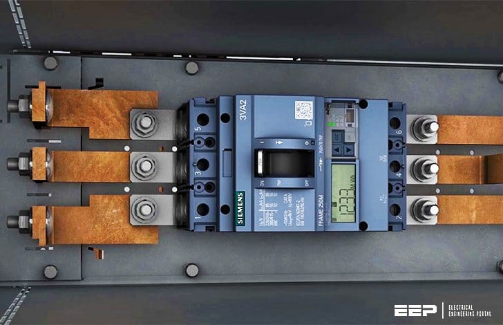
Typical molded-case circuit breakers are shown in Figure 1, where on the left is a thermal-magnetic circuit breaker, and on the right is an electronic-trip circuit breaker. The thermal-magnetic circuit breaker is designed for cable connections and the electronic circuit breaker is designed for bus connections, but neither type is inherently suited for one connection type over another.
Circuit breakers may be mounted in stand-alone enclosures, in switchboards, or in panelboards.

Thermal-magnetic circuit breaker time-current characteristic
A typical thermal-magnetic circuit breaker time-current characteristic is shown in figure 2.
Note also that there is a band of operating times for a given fault current. The lower boundary represents the lowest possible trip time and the upper boundary represents the highest possible trip time for a given current.

Electronic-trip circuit breaker time-current characteristic
The time-current characteristic for an electronic-trip circuit breaker is shown in figure 3. The characteristic for an electronic trip circuit breaker consists of the long time pickup, long-time delay, short-time pickup, short time delay, and instantaneous pickup parameters, all of which are adjustable over a given range.
This adjustability makes the electronic-trip circuit breaker very flexible when coordinating with other devices. The adjustable parameters for an electronic trip circuit breaker are features of the trip unit.
In many cases the trip unit is also available without the short-time function.
For circuit breakers that have a short-time rating, the instantaneous feature may be disabled, enhancing coordination with downstream devices.

If the instantaneous feature has been disabled one must still be cognizant of any instantaneous override feature the breaker has, which will engage the instantaneous function above a given level of current even if it has been disabled in order to protect the circuit breaker from damage.
Coordination
Typical coordination between an electronic and a thermal magnetic circuit breaker is shown in figure 4 below. Because the time bands do not overlap, these two devices are considered to be coordinated.

A further reduction in the let-through energy for a fault in the region between two electronic-trip circuit breakers can be accomplished through zone-selective interlocking. This consists of wiring the two trip units such that if the downstream circuit breaker senses the fault (typically this will be based upon the short-time pickup) it sends a restraining signalto the upstream circuit breaker.
The upstream circuit breaker will then continue to time out as specified on its characteristic curve, tripping if the downstream device does not clear the fault.
However, if the downstream device does not sense the fault and the upstream devices does, the upstream device will not have the restraining signal from the downstream device and will trip with no intentional delay.
Example
For example, if zone selective interlocking were present in the system of figure 4 and fault occurs on bus C circuit breaker B will sense the fault and send a restraining signal to circuit breaker A. Circuit breaker A is coordinated with circuit breaker B, so circuit breaker B will trip first.
If circuit breaker B fails to clear the fault, circuit breaker A will time out on its time-current characteristic per figure 4 and trip. If the fault occurs at bus B, circuit breaker B will not detect the fault and thus will not send the restraining signal to circuit breaker A. Circuit breaker A will sense the fault and will trip with no intentional delay, which is faster than dictated by its time-current characteristic per figure 4.
Care must be used when applying zone-selective interlocking where there are multiple sources of power and fault currents can flow in either direction through a circuit breaker.
Table 1 shows typical characteristics of molded-case circuit breakers for commercial and industrial applications. This table is for reference only; when specifying circuit breakers manufacturer’s actual catalog data should be used.
| Frame Size (A) | Number of Poles | Interrupting Rating at AC voltage (kA, RMS symmetrical) | ||||
| 120 V | 240 V | 277 V | 480 V | 600 V | ||
| 100 | 1 | 10 | 14 | |||
| 1 | 65 | 65 | ||||
| 100, 150 | 2, 3 | 18 | 14 | 14 | ||
| 2, 3 | 65 | 25 | 18 | |||
| 2, 3 | 100 | 65 | 25 | |||
| 225, 250 | 2, 3 | 25 | 22 | 22 | ||
| 2, 3 | 65 | 25 | 22 | |||
| 2, 3 | 100 | 65 | 25 | |||
| 400, 600 | 2, 3 | 42 | 30 | 22 | ||
| 2, 3 | 65 | 65 | 25 | |||
| 2, 3 | 100 | 35 | ||||
| 800, 1000 | 3 | 42 | 30 | 22 | ||
| 65 | 50 | 25 | ||||
| 200 | 100 | 65 | ||||
| 1200 | 3 | 42 | 30 | 22 | ||
| 3 | 65 | 50 | 25 | |||
| 3 | 200 | 100 | 65 | |||
| 1600, 2000 | 3 | 65 | 50 | 42 | ||
| 3 | 125 | 100 | 65 | |||
| 3000, 4000 | 3 | 100 | 100 | 85 | ||
| 3 | 200 | 150 | 100 | |||
Note that the continuous current rating is set by the sensor and rating plug sizes for a given electronic-trip circuit breaker. This can be smaller than the frame size. As can be seen from table 1, more than one interrupting rating can be available for a given frame size.
Current-limiting circuit breakers are also available. Coordination between two current-limiting circuit breakers when they are both operating in the current limiting range is typically determined by test.
Magnetic-only circuit breaker swhich have only magnetic tripping capability are available. These are often used as short-circuit protection for motor circuits. For this reason these are often referred to as motor circuit protectors.
Reference: System Protection – Bill Brown, P.E., Square D Engineering Services
Related electrical guides & articles


Edvard Csanyi
Hi, I'm an electrical engineer, programmer and founder of EEP - Electrical Engineering Portal. I worked twelve years at Schneider Electric in the position of technical support for low- and medium-voltage projects and the design of busbar trunking systems.I'm highly specialized in the design of LV/MV switchgear and low-voltage, high-power busbar trunking (<6300A) in substations, commercial buildings and industry facilities. I'm also a professional in AutoCAD programming.
Profile: Edvard Csanyi

Can I use 24..30VAC/DC rated voltage motor operators of 690VAC MCCB instead of 220…250VAC/DC motor operators? What makes the difference technically?
that is very helpefull uinformation.thankes to my friend
what is the difference between reaking and the current rating of a MCCB
Can you please design an application for windows phones? I am using a microsoft windows 8.1 phones and would like to have EEP App .
very informative and interesting. thank you for this article & i need to read more :)
Very helpful, easy to understand, makes explaining to trainees a lot easier.