
Estimated Study Time: 8 minutes
Why we don’t like reactive power
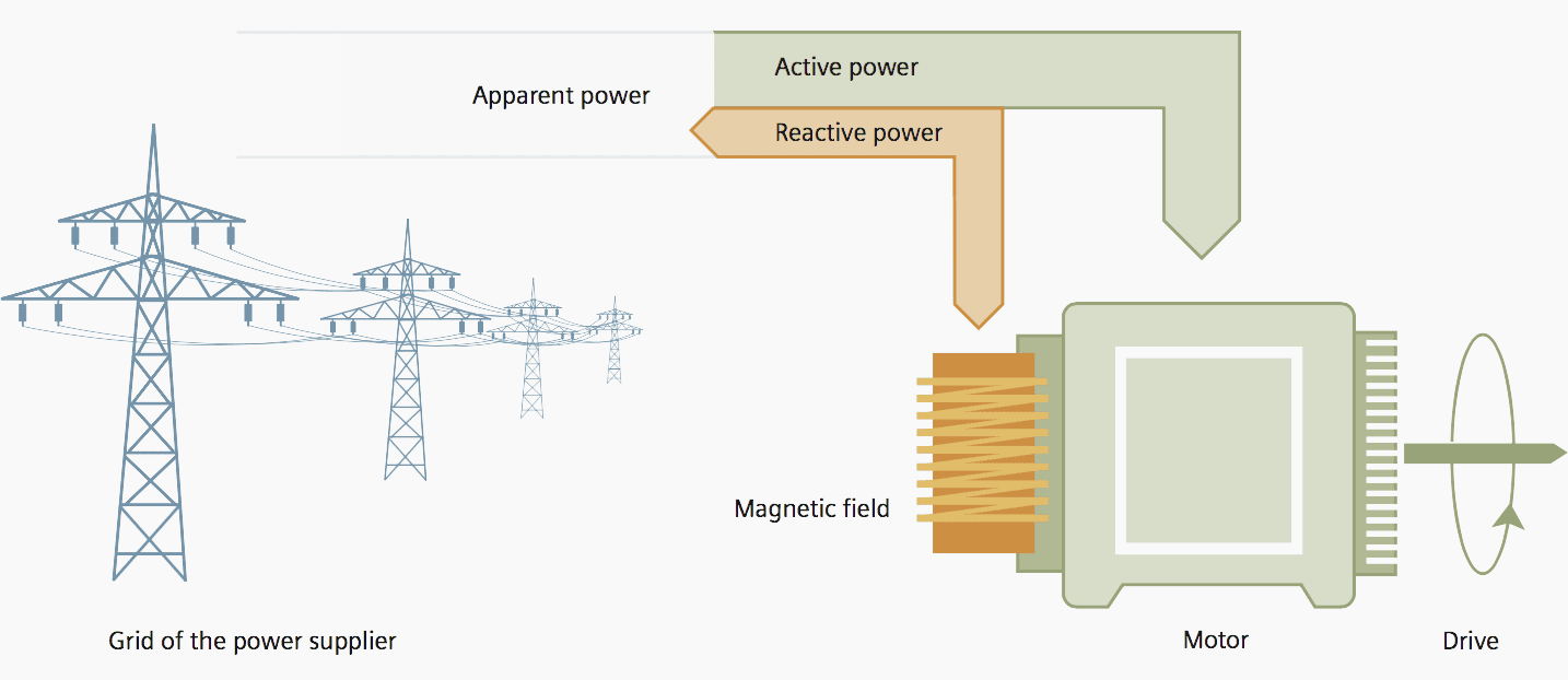
The total power, the so-called apparent power, of a transmission network is composed of active and reactive power (Figure 1). While the power consumers connected into supply transform the active power into active energy, the reactive energy pertaining to the reactive power is not consumed.
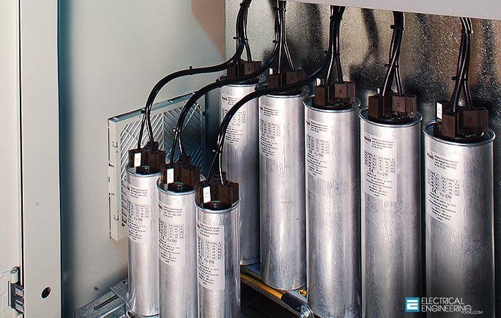 Reactive Power and Compensation Solutions Basics For Students (photo credit: eltrex.ro)
The reactive power at the consumer side is merely used for building up a magnetic field, for example, for operating electric motors, pumps, or transformers.
Reactive power is generated when power is drawn from the supply network and then fed back into the network with a time delay.
This way it oscillates between consumer and generator. This constitutes an additional load on the network and requires greater dimensioning in order to take up the oscillating reactive power in addition to the active power made available. As a consequence, less active power can be transported.
Reactive power has zero average value because it pulsates up and down, averaging to zero. Reactive power is measured as the maximum of the pulsating power over a cycle. It can be positive or negative, depending on whether current peaks before or after voltage.
By convention, reactive power, like real power, is positive when it is “supplied” and negative when it is “consumed”. Consuming reactive power lowers voltage magnitudes, while supplying reactive power increases voltage magnitudes.
Solution with compensation //
With a reactive power compensation system with power capacitors directly connected to the low voltage network and close to the power consumer, transmission facilities can be relieved as the reactive power is no longer supplied from the network but provided by the capacitors (Figure 2).
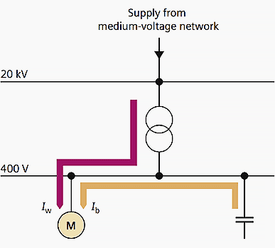
Transmission losses and energy consumption are reduced and expensive expansions become unnecessary as the same equipment can be used to transmit more active power owing to reactive power compensation.
Determination of capacitor power
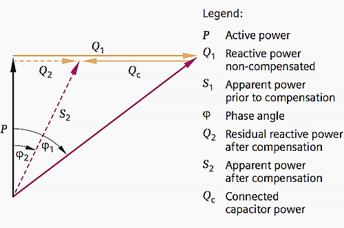
A system with the installed active power P is to be compensated from a power factor cos φ1 to a power factor cos φ2. The capacitor power necessary for this compensation is calculated as follows:
Qc = P · (tan φ1 – tan φ2)
Compensation reduces the transmitted apparent power S (see Figure 3). Ohmic transmission losses decrease by the square of the currents.
Reactive power estimate
For industrial plants that are still in a configuring stage, it can be assumed by approximation that the reactive power consumers are primarily AC induction motors working with an average power factor cos φ ≥ 0.7. For compensation to cos φ = 0.9, a capacitor power of approximately 50 % of the active power is required:
Qc = 0.5 · P
In infrastructural projects (offices, schools, etc.), the following applies:
Qc = 0.1 to 0.2 · P
Calculation of the reactive power
(Based on the electricity bill)
For installations which are already running, the required capacitor power can be determined by measuring. If active and reactive work meters are available, the demand of capacitor power can be taken from the monthly electricity bill.
tan φ = reactive work / active work
For identical meter operating times in the measurement of reactive and active work //
tan φ = reactive power Q / active power P with
tan φ = √(1 – cos2 φ) / cos φ
The compensation power Qc matching the active power P can be calculated for a desired value of cos φ2.
Qc = Q1 – Q2 = P · F
In this case F = tan φ1 – tan φ2
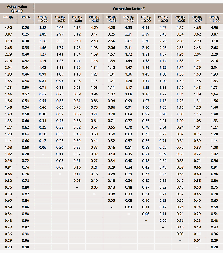
To simplify the calculation of Qc, Table 1 states the conversion factors F when a measured cos φ1 is to be compensated in order to attain a power factor cos φ2 in operation.
3 main types of compensation //
Capacitors can be used for single, group, and central compensation. These types of compensation will be introduced in the following //
Single compensation
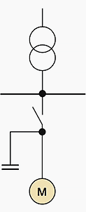
In single compensation, the capacitors are directly connected to the terminals of the individual power consumers and switched on together with them via a common switching device. Here, the capacitor power must be precisely adjusted to the respective consumers. Single compensation is frequently used for induction motors (Figure 4).
Single compensation is economically favourable for:
- Large individual power consumers
- Constant power demand
- Long ON times
Group compensation
With group compensation, each compensation device is assigned to a consumer group. Such a consumer group may consist of motors or discharge lamps, for example, which are connected into supply together through a contactor or switch. In this case, special switching devices for connecting the capacitors are not required either (Figure 5).
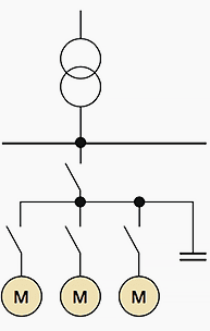
Group compensation has the same advantages and disadvantages as single compensation.
Central compensation
Reactive power control units are used for central compensation, which are directly assigned to a switchgear unit, distribution board, or sub-distribution board and centrally installed there. Control units contain switchable capacitor branch circuits and a controller which acquires the reactive power present at the feed-in location.
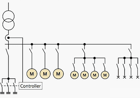
If it deviates from the set-point, the controller switches the capacitors on or off step by step via contactors.
The capacitor power is chosen in such a way that the entire installation reaches the desired cos φ (Figure 6). Central compensation is recommended in case of:
- Many small power consumers connected into supply
- Different power demands and varying ON times of the power consumers
References //
- Planning of Electric Power Distribution by SIEMENS
- Principles for Efficient and Reliable Reactive Power Supply and Consumption by Federal Energy Regulatory Commission
Related electrical guides & articles


Edvard Csanyi
Hi, I'm an electrical engineer, programmer and founder of EEP - Electrical Engineering Portal. I worked twelve years at Schneider Electric in the position of technical support for low- and medium-voltage projects and the design of busbar trunking systems.I'm highly specialized in the design of LV/MV switchgear and low-voltage, high-power busbar trunking (<6300A) in substations, commercial buildings and industry facilities. I'm also a professional in AutoCAD programming.
Profile: Edvard Csanyi

reactive power in the system increases the overall Apparent Power. increase the system
overall Power increases Current I. in case of this falling of voltage or declination of system voltage will be increases .
Consuming reactive power increases the Apparent Power. We all know that increase in Apparent Power increases Current I. Increase in current increases the voltage drop and lowers the voltage profile.
Dear Edvard,
Can you explain this question:
“Why consuming reactive power lowers voltage magnitudes?”
very nice explanation thank you very much for your contribution
Great piece. Well written and summarised for a high level view on compensation solutions. Thanks for highlighting here.
OK
ho to a Premium Membership?
and how much a year?
thank you
Veey Good knowledge sharing and knowing new things from your site, thank you for your support
I would like to engage knowlage from your site
Very Helpful sir.
I have been doing power factor correction for few years now.
However I have this concern about an argument raised by a friend, that compensation capacitors have a positive effect on heating equipment. That it increases the heating power and saves time needed to reach a certain temperature for industrial heaters.
Please comment
Compensating with capacitors will not increase the heating power directly as it is a Resistive load and will not draw any reactive power.It is like this when u have combined Resistive and Inductive load and power factor is low and Apparent power is high, Voltage drop is high and voltage profile is low. By compensating with capacitors the voltage profile is high which may be helping in heating up due to good voltage profile. This is visible when u compensate at the load ends which are highly inductive
very nice explanation thank you very much for your contribution
Hi Edvard
Thanks for such an informative topic
Thank you very much for these valuable information . I really was looking for these information
You are welcome Osama, I’m glad you found what you were looking for!
It is indeed a very good article. Very nicely & simply explaining role of reactive power and how to deal with it. Students will find it vey helpful in understanding the concept.
I suggest support it with video (not of people explaining it but) of active power and reactive power demonstrating their relation and compensation.
THIS IS BASIC FOR THE ELECTRICAL ENGINEERS IN OUR FIELD
I FIND A LOT OF THE ELECTRICAL ENGINEEERS DO NOT KNOW ABOUT THIS .
MAY BE THEY THOUGTH THAT PHYSICS WAS NOT IMPORATANT.
IF YOU ARE IN THE POWER BUSINESS YOU SHOULD KNOW ABOUT POWER FACTOR, RLC CKTS, BECAUSE THERE ARE INHERENT IN ANY PART OF ELECTRICAL CIRCUI.TS. FROM WIRE , TO MOTORS , TO TRFMR, TO TV , COMMUNICATIONS, ELECTRONICS, NON -LINEAR CIRCUITS ETCETERA, ETCETERA.
GOOD BLESS