
Estimated Study Time: 33 minutes
Reactive power injection
When reactive power devices, whether capacitive or inductive, are purposefully added to a power network in order to produce a specific outcome, this is referred to as compensation. It’s as simple as that. This could involve greater transmission capacity, enhanced stability performance, and enhanced voltage profiles as well as improved power factor. The reactive devices can be connected either in series or in parallel (shunt).
 Do you know what reactive power compensation is? If not, keep reading, it's important.
Before we get into the depth of describing the compensation applications and other details, let’s remind ourselves of the power flow basics.
As you can see from Figure 1, the flow of power in an electric circuit is illustrated. The link has an impedance of R+jX, and we assume that V1>V2 and that V1 leads V2. In most power networks, X>>R, and reactive power flows from A to B. The direction of reactive power flow can be reversed by making V2>V1.
The magnitude of reactive power flow is determined by the voltage difference between point A and B. When R is ignored, the reactive power flow, Q is given by the following formula:
Q = V2(V1 − V2) / X
The ideal situation is when V1 = V2, and reactive power flow is zero.
Figure 1 – Typical power flows in electric circuits

The maximum possible active power transfer Pmax is given by Pmax = V1V2 / X. It is clear from the above formula that active power transfer capacity is improved if V2 is increased.
Ok, let dive now into reactive power devices, their diagrams, phasor diagrams, applications, do’s and don’ts and other important cautions.
- Series capacitors
- Shunt capacitors
- Shunt reactors
- Synchronous compensators
- Static VAR compensators
- Distribution applications of shunt capacitors
- Caution! Effect of shunt capacitors on induction motors
1. Series capacitors
Series capacitors are utilized to neutralize part of the inductive reactance of a power network. This is illustrated in Figure 2. From the phasor diagram in Figure 3 we can see that the load voltage is higher when the capacitor is inserted in the circuit.
Figure 2 – Use of series capacitors to neutralize inductor reactors
Figure 3 – Phasor diagram with series capacitor in circuit
Introducing series capacitance in the network reduces the net reactance X, and increases the load voltage, with the result that the circuit’s transmission capacity is increased, as can be seen from equation Q = V2(V1 − V2) / X.
Series capacitors have the following benefits to the network:
- Improved voltage conditions
- Enhanced stability performance
- Controlling reactive power balances
- Aid in load distribution and control of overall transmission losses.
Due to the added transmission capacity, series-capacitor compensation may delay investments in additional overhead lines and transmission equipment, which can have capital investment benefits to the utility company as well as environmental impact advantages.
A 33 kV, 1.25 MVAr capacitor bank on the New York Power and Light system served as the first series-capacitor installation in history in 1928. Since then, numerous higher-rated systems have been deployed all around the globe.
Energy is then exchanged between the electrical and mechanical systems at one or more natural frequencies of the combined system below the synchronous frequency of the system. Increasing mechanical oscillations can occur resulting in eventual mechanical failure of the turbine-generator system.
The following are techniques to counteract SSR:
Technique #1 – Supplementary excitation control: The sub-synchronous current and/or voltage is detected and the excitation current is modulated using high-gain feedback to vary the generator output voltage, which counters the sub-synchronous oscillations.
Technique #2 – Static filters: These are tuned to correspond to the power system frequency to filter out the oscillation mode frequencies. They are normally connected in series with each phase of the generator(s).
Technique #3 – Dynamic filters: In a manner similar to that of excitation control, the subsynchronous oscillations are detected, a counter Electromotive force (EMF) is generated and injected into the power network through a series transformer to neutralize the unwanted oscillations.
Technique #4 – Bypassing series capacitors: To limit transient torque build-up.
Technique #5 – Amortisseur windings on the pole faces of the generator rotors can be employed to improve damping.
Technique #6 – A passive SSR countermeasure scheme involves using three different combinations of inductive and capacitive elements on the three phases. The combinations will have the required equal degree of capacitive compensation in the three phases at the power frequency.
At any other frequency, the three combinations will appear as unequal reactance in the three phases.
The following points are worth noting when considering the merits of series capacitors:
- Series capacitors are very effective when the total line reactance is high.
- Series capacitors are effective to compensate for voltage drop and voltage fluctuations.
- Series capacitors are of little value when the reactive power requirements of the load are small.
- In cases where thermal considerations limit the line current, series capacitors are of little value since the reduction in line current associated with them is relatively small.
In the last two points (3, 4) mentioned above, shunt capacitors may be considered instead of series capacitors.
Suggested Course – The Essentials of Capacitor Banks: Connections, Calculations and Relay Protection
The Essentials of Capacitor Banks: Connections, Calculations and Relay Protection
Go back to the Contents Table ↑
2. Shunt capacitors
Shunt capacitors supply capacitive reactive power to the system at the point where they are connected, mainly to counteract the out-of-phase component of current required by an inductive load. They may either be energized continuously or switched on and off during load cycles.
Figure 4 illustrates a circuit with shunt capacitor compensation applied at the load side.
Figure 4 – Use of shunt capacitors to counteract out-of-phase current component
Referring to the phasor diagram of Figure 5, the line current IL is the sum of the motor load current IM and the capacitor current IC.
Figure 5 – Current phasor diagram

It can be seen that the line current is decreased by adding the shunt capacitor. The angle between the load voltage and current is decreased from φ2 to φ1. Figure 6 displays the corresponding voltage phasors. The result of adding the shunt capacitance is to decrease the source voltage from Vs1 to Vs2.
Figure 6 – Voltage phasor diagram

It can be seen from the above that the application of shunt capacitors in a network with a lagging power factor has the following benefits:
- Increase voltage level at the load
- Improve voltage regulation (if the capacitors are switched in and out of the network correctly)
- Reduce I2R active power loss and I2X reactive power loss due to the reduction in current
- Increase power factor
- Decrease kVA (or mVA) loading on the source generators and network to relieve an overload condition or make capacity available for additional load growth
- Reduce demand kVA where power is purchased
- Reduce investment in system facilities per kW of load supplied.
Note that in determining the amount of shunt capacitance required, some additional capacitive kVAr above that based on initial conditions without capacitors may be required. This is due to the fact that a voltage rise increases the lagging kVAr in the exciting currents of transformers and motors.
Go back to the Contents Table ↑
2.1 Caution worth mention
Increased harmonics on the power system and/or a harmonic resonance condition may result with applying capacitors, especially when using harmonic-generating apparatus, such as thyristor controllers. Either a shunt or series resonance condition, or a combination of both, may occur if the resonant point happens to be close to one of the frequencies generated by harmonic sources in the system.
This can result in excessive harmonic currents flowing or harmonic overvoltages, or both, causing possible operation of the capacitor protection equipment (such as fuses), capacitor failure, overheating of other electrical equipment and electrical system interference.
Go back to the Contents Table ↑
3. Shunt reactors
Shunt reactor compensation is usually required under conditions that are the opposite of those requiring shunt capacitor compensation. This is illustrated in Figure 7.
Shunt reactors may be installed in the following conditions:
- To compensate for overvoltages occurring at substations served by long lines during low-load periods, as a result of the line’s capacitance (Ferranti effect as voltage tip up).
- To compensate for leading power factors at generating plants, resulting in lower transient and steady-state stability limits.
- To reduce open-circuit line charging kVA requirements in extra high-voltage (EHV) systems.
The effect of shunt reactance on the current phasor diagram is shown in Figure 8.
Figure 7 – Shunt reactor compensation
Figure 8 – Effect of shunt reactors

Go back to the Contents Table ↑
4. Synchronous compensators
A synchronous compensator is a synchronous motor running without a mechanical load. It can absorb or generate reactive power, depending on the level of excitation. When used with a voltage regulator, the motor can run automatically over-excited at high-load current and under-excited at low-load current.
The cost of installation of synchronous compensators is high compared to capacitors, and the electrical losses are considerable relative to capacitors.
Synchronous condensers can also be used as dip mitigation devices to support the voltage during drops.
Suggested Guide – Synchronous machines (generator and motor) in a nutshell
Go back to the Contents Table ↑
5. Static VAR compensators
Static VAR compensators (SVCs) contain shunt capacitors and reactors, which are controlled by thyristors. They provide solutions to two types of compensation problems normally encountered in practical power systems:
The first is load compensation, where the requirements usually are to reduce the reactive power demand of large and fluctuating industrial loads, and to balance the real power drawn from the supply lines.
The second type of compensation is related to voltage support of transmission lines at a certain point in response to disturbances of both load and generation. The main objectives of dynamic VAR compensation are to increase the stability limit of the power system, to decrease voltage fluctuations during load variations and to limit overvoltages due to large disturbances.
The two fundamental thyristor-controlled reactive power device configurations are:
5.1 Thyristor-switched shunt capacitors
The capacitor bank is split into small capacitor steps and those steps are switched on and off individually. It offers stepwise control, virtually no transients and very little harmonic generation. The average delay for executing a command from the regulator is half a cycle.
Figure 9 shows this arrangement.
Figure 9 – Thyristor-switched shunt capacitors

5.2 Thyristor-switched shunt reactors
The fundamental frequency current component through the reactor is controlled by delaying the closing of the thyristor switch with respect to the natural zero crossings of the current. Figure 10 illustrates this concept.
Harmonic currents are generated from the phase-angle-controlled reactor. There are two methods to reduce the magnitude of the generated harmonics. The first method consists of splitting the reactor into smaller steps, with only one thyristor-controlled step while the other reactor steps are either on or off.
Thyristor-switched reactors are characterized by continuous control, and there is a maximum of one half-cycle delay for executing a command from the regulator.
Figure 10 – Thyristor-switched shunt reactors
In many practical applications, a combination of these two thyristor-controlled devices are used, with the SVC consisting of a few steps of thyristor-controlled capacitance and one or two thyristor-controlled reactors, as shown in Figure 4.9 (c).
Figure 11 – A combination of these two thyristor-controlled devices
It is important to note that applying static VAR compensators to series-compensated AC transmission lines results in three distinct resonant modes:
- Shunt capacitance resonance: It involves energy exchange between the shunt capacitance (line charging plus any power factor correction and SVCs) and the series inductance of the lines and the generator.
- Series-line resonance: It involves energy exchange between the series capacitor and the series inductance of the lines, transformers and generators.
- Shunt-reactor resonance: It involves energy exchange between shunt reactors at the intermediate substations of the line and the series capacitors.
Due to the above, it is crucial to represent any compensators in transient electrical simulation programs.
Go back to the Contents Table ↑
6. Distribution applications of shunt capacitors
Shunt capacitors are used more frequently in power distribution systems than any other electrical compensation device. They are used mostly for voltage regulation and power factor correction; hence, these two specific applications will be briefly discussed.
6.1 Voltage regulation
Voltage drop can be reduced by the application of a shunt capacitor. A correct selected and located shunt capacitor assures that the voltage at the load will be within the allowable limit at the heavy load condition.
However, at light loading, the same capacitor will increase the voltage to above the allowable limit, as illustrated in Figure 12.
Figure 12 – Capacitor effect on voltage
The way to avoid this is to use switched capacitor banks. The capacitors are switched in during heavy load conditions and switched out during light load conditions. When the capacitor(s) is switched in, the capacitive current is added to the inductive current, reducing total current, voltage drop and electrical losses.
The last is due to reducing reactive power in the system (see next paragraph).
The optimum number, size and location of capacitor banks on a feeder are determined by detailed computer analysis, also taking into consideration minimization of the operation, installation and investment costs. The most important factors that affects the selection is the voltage levels, total loading, distribution factor and power factor of loads.
Suggested Course – Power System Analysis: The Essentials of Load Flow and Short Circuits
Power System Analysis Course: The Essentials of Load Flow and Short Circuits
Go back to the Contents Table ↑
6.2 Power factor correction
6.2.1 Power and power factor
Power in a three-phase distribution system consisting of two components, namely active or real power (P) and reactive power (Q). The complex sum of the two gives apparent power (S). Hence, S = P + jQ.
This is illustrated in the well-known power triangle in Figure 13.
Figure 13 – Power triangle

Apparent power (S) in a three-phase system is calculated by the formula, S = √3VI. This is expressed in VA, kVA or MVA, and is the unit used for the ratings of transformers. Power cables and transformers add reactance to a power network, which is mainly inductive (a lesser amount of capacitance is also added).
The inductive and capacitive reactances are frequency dependent (hence are only present in AC systems), oppose each other and are at right angles to the pure (DC) resistance. The net reactance, which is usually inductive, opposes the flow of current, and the power required to overcome this reactance is called reactive power (Q). This is wasted power, which is of no benefit to the user.
Reactive power is calculated by the formula, Q = √3Visin φ, and is expressed in VAr, kVAr or MVAr.
Power factor correction
The presence of reactance in the network causes the voltage and the current phasors at the load to move out of phase by the phase angle φ . (The voltage phasor is taken as the reference, and the current phasor is then defined as ‘lagging’ with respect to a counterclockwise phase rotation.)
The cosine of the phase angle (cos φ) is known as the power factor.
The longer the cables and the more transformers in a distribution network, the more inductive reactance is present in the network, the greater the phase angle (lower power factor) and the higher the losses. Adding capacitance to an inductive network will serve to decrease the phase angle (φ), improve the power factor (cos φ) and result in a more efficient distribution network.
This is known as power factor correction.
When more capacitive than inductive reactance is present in the network, a leading phase angle may result, with the current phasor leading the voltage phasor. A leading phase angle will have detrimental effects on the operation of induction motors, and must be avoided.
Active power is the electrical power available to be utilized usefully, and is expressed in W, kW or MW. This is the unit in which electric motors, lights, heaters, etc. are rated.
Active power is expressed by the formula P = √3 × V × I × PF(load), where PF = cos φ.
Suggested Course – AC Circuits Analysis: Real, Reactive and Complex Power Calculation
AC Circuits Analysis: Real, Reactive and Complex Power Calculation
Go back to the Contents Table ↑
6.2.2 Causes and effects
Any equipment with inductive properties will worsen the power factor, as reactive power is used to overcome the inductive reactance. Therefore, induction motors, transformers and cables will all add to increase φ. In addition, variable speed drives that use waveform ‘chopping’ will also worsen the power factor due to the distortion of the current waveforms, in addition to adding harmonics to the system.
The effect of a low-power factor at the load is that more current is required to achieve the same power output, as can be seen from the power formulae.
The following is an example of the effect of low-power factor:
- Required active power: 200 kW
- Operating voltage: 415 V
- PF = 0.85
- I = 200,000 / (1.732 × 415 × 0.85) = 327 A
- PF = 0.55
- I = 200,000 / (1.732 × 415 × 0.55) = 506 A
It can be seen from the above example that power factor has a substantial effect on the magnitude of current flowing in the network.
A sustained low-power factor may have the following effects:
- Overheating of equipment due to the excess current flowing
- Equipment being over-rated to compensate for higher currents flowing due to low-power factor
- Higher electricity consumption when measured in VA
- Necessitate additional investment in system facilities to obtain the required kW
- Lower voltage level at the load (see Section 4.7)
- Increased power losses (resistive and reactive) throughout the system due to higher currents flowing.
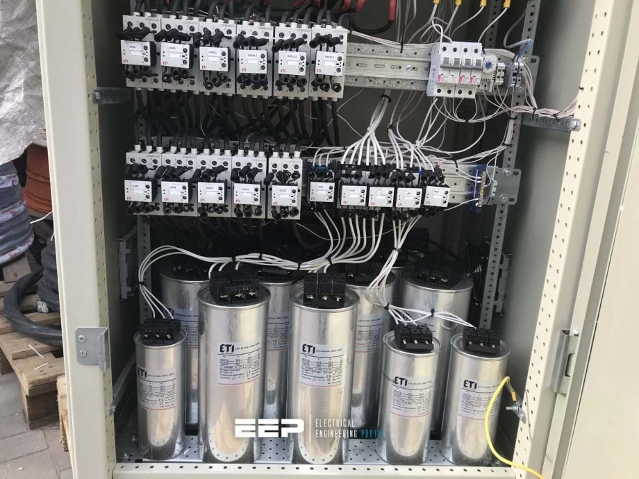
Good Reading – Inside the capacitor bank panel: Power factor correction, calculation and schematics
Inside the capacitor bank panel: Power factor correction, calculation and schematics
Go back to the Contents Table ↑
6.2.3 Tariff example
Many countries’ electricity utilities introduced a penalty charge for customers with low-power factor. Several countries have changed from a kW tariff to a kVA tariff for maximum demand. A low-power factor will have a direct influence on the amount of total kVA a company will use to obtain a certain amount of active kW power (kVA = kW + jkVAr [complex values]).
The lower the power factor, the more VARs are consumed.
Let us look at an example:
To simplify the calculation for illustration purposes, we assume average values. A factory’s average monthly maximum demand is 100 MW at a power factor of 0.65. The power triangle for this situation is shown in Figure 14 (a).
For a power factor of 0.65 and real power (P) of 100 MW, the apparent power (S) is 153.846 MVA and reactive power (Q) is 116,913 MVAR (as we know that P=S×cosφ; Q=S×sinφ).
As can be noted, the reactive power in the network is of a higher value than the real power!
Figure 14 – Example power triangle

Referring to Figure 14 (b), to increase the power factor to 0.8 would need 41,913 kVAR. Therefore, the factory would be charged $0.3757×30×41,913 = $472,401.42 over a month period, which could be avoided by increasing the power factor to 0.8! This should be more than enough economic justification to install power factor correction (PFC) equipment.
Approving power factor also have added benefits, like reduced active and reactive losses due to the reduction in the magnitude of currents flowing.
Go back to the Contents Table ↑
7. Caution: effect of shunt capacitors on induction motors
Capacitors installed close to induction motors can have the following effects:
- Increasing undesirable torque transients on the rotor
- Self-excitation and capacitive braking.
7.1 Torque transients
A short voltage interruption can cause severe torque peaks in the rotor of an induction motor. In the worst case, this can be more than 20 times the full load torque, and in the direction opposite to the rotation of the rotor. Under loaded conditions, this ‘reverse torque’ can easily cause severe mechanical damage to the rotor shaft.
The presence of capacitance in the system, especially power factor correction capacitors directly on the motor terminals, will worsen the condition substantially.
Good Reading! – Never let an electric motor drop dead. Learn how to listen and read the motor’s soul.
Never let an electric motor drop dead. Learn how to listen and read the motor’s soul.
Go back to the Contents Table ↑
7.2 Explanation of ‘reverse torque’
When a running motor is disconnected from the power supply, a trapped or ‘frozen’ flux is carried round with the rotor. This flux decays, but induces a rotational Electromotive force (EMF) in the stator windings. When the power supply returns while the rotor is still turning, the induced stator EMF may have phase-opposition to the supply voltage at the instant of reconnection.
This will cause severe transients currents and torque, depending on the magnitude of the induced stator EMF still present and the degree of phase-opposition. The transient torque so developed may have a negative (retarding) peak.
The capacitors tend to maintain the gap flux when the supply is interrupted, and the stator may build up an overvoltage in spite of the drop in rotor speed. When the supply is reconnected with a phase-opposition to the induced stator EMF, very severe current and torque transients will occur. The resultant first transient torque peak may exceed 20 times full load torque.
Normally, the control voltage for the main contactor feeding an induction motor is transformed directly from the main supply voltage. The capacitors connected to the stator terminals will tend to keep the voltage level up during a power interruption, which will in turn keep the contactor coil energized, preventing the contactor from opening.
Therefore, when the supply voltage comes back after a short period of time, it is directly applied to the stator, possibly opposing the induced EMF already there. To prevent connected shunt capacitors from worsening the torque transients during voltage interruptions, the capacitor(s) can be disconnected automatically during a severe voltage interruption.
The following is a graphical illustration of the transient torque occurrence (Figure 15):
Figure 15 – Transient torque occurrence graph

Go back to the Contents Table ↑
7.3 Self-excitation and capacitive braking
With the magnetizing reactive power provided by a capacitor bank, provided that the rotor has an adequate remnant field, an induction motor may self-excite upon the loss of stator supply. This results in the motor functioning as an induction generator, and stator overvoltages may occur. The capacitance value of power factor correction capacitors may have to be limited to prevent self-excitation.
Self-excitation may be purposely used under controlled conditions for braking. On disconnection of the stator from the supply and its subsequent connection to a capacitor bank, the stator voltages are self-excited to develop a travelling-wave field, and for a generating mode the ‘synchronous’ speed of the field must be lower than the speed of rotor rotation.
The drive power is drawn from the inertia energy and the speed consequently falls rapidly.
However, for high-inertia loads that stay mechanically connected to the rotor shaft, forced braking may be undesirable and may even lead to rotor shaft damage.
Suggested Reading – Inside Variable Frequency Drive (VFD) Panel: Configuration, Schematics and Troubleshooting
Inside Variable Frequency Drive (VFD) Panel: Configuration, Schematics and Troubleshooting
Go back to the Contents Table ↑
Source: Practical Power Distribution for Industry by Jan de Kock and Kobus Strauss
Related electrical guides & articles


Edvard Csanyi
Hi, I'm an electrical engineer, programmer and founder of EEP - Electrical Engineering Portal. I worked twelve years at Schneider Electric in the position of technical support for low- and medium-voltage projects and the design of busbar trunking systems.I'm highly specialized in the design of LV/MV switchgear and low-voltage, high-power busbar trunking (<6300A) in substations, commercial buildings and industry facilities. I'm also a professional in AutoCAD programming.
Profile: Edvard Csanyi

very good topic
dear sir
what is happen to the system if the power factor is it will go capacitance ?
thanks
Very informative and knowledgeable portal to belong.
Kindly assist me with information on symmetrical and u symmetrical faults.
Very informative and indepth.
I want to thank you for being innovative sothat power used in the system is quality power
which improves the performance of industrial machines and domestic power machines.
However i have been trying to register as a Premium member but i have failed , let someone out there give me a hand.
thank you
Your courses are very helpfull but could you provide the solution of the problem in our distribution system regarding relay and phasor diagram