
Estimated Study Time: 14 minutes
Compensation of reactive power
Compensation of reactive power applied in buildings or small facilities operates in the first and second quadrants of the coordinate system. Increasingly, complex industrial plants, for example plants burning wood dust, are using generators driven by steam engines running parallel to the main supply.
 Reactive power compensation in electrical plants with generators (photo credit: ingelmec.com.pe)
This technical article explains the technical and economic aspects regarding the desired power factor or reactive energy to be charged. If generators are feeding back active energy to the distribution company, one speaks of four-quadrant operation.
The tariff situation then has new aspects with regard to the reactive energy consumption to be charged. The tariff requiring an average power factor of cos φ = 0.9 lagging becomes invalid as explained in the following paragraphs.
Furthermore, it renders prominent the meanings of power factor cos φ and reactive power Q as totally different electro-physical quantities. One could describe them in an inequality like:
cos φ ≠ Q ≠ cos φ
Thus power factor is not identical to reactive power and vice versa.
- The complexity of putting generator(s) into action
- Automatic control of reactive power within four quadrants
- Conclusions
1. The complexity of putting generator(s) into action
Any plan for putting generator(s) into action must be declared to the electricity supplier and registered in a specially negotiated contract. It determines to which incoming supply (if more than one) the generator should be connected. Specifications issued by national or international institutions should be strictly followed.
First of all, power generator units running steadily in parallel to the main supply must be distinguished from emergency power generator units at hospitals that are activated in case of any fault or collapse in the main supply. Emergency power generator units are in use for a short time, mainly until the grid is active again. This situation may be excluded by referring to four-quadrant operation.
The following criteria on driving generators in parallel to the grid are to be noted: voltage stability, quality of the voltage and synchronized frequency. It must further be taken into consideration whether an autarchic operation will be intended.
However, this is possible mainly with synchronous generators.
Go back to Table of Contents ↑
2. Automatic Control of Reactive Power within Four Quadrants
2.1 Technical Considerations
Figure 1 illustrates the four quadrants of a coordinate system. If generators are in operation four different load situations may occur:
- Quadrant I: Consumers import (+) active and reactive energy.
- Quadrant II: Consumers import (+) active energy and export (−) reactive energy.
- Quadrant III: Consumers export (−) active and reactive energy.
- Quadrant IV: Consumers export (−) active energy but import (+) reactive energy.

In quadrants III and IV the generators are feeding back active energy to the electricity supplier to be measured by a separate kWh-meter.
Most attention is paid to the situation within quadrant IV! Asynchronous generators especially are able to feed back active energy to the grid, but they import reactive energy for magnetizing!
The situation in quadrants I and II is well known and can be referred as a standard. There the control of reactive power is explained by means of an automatic controller. One can recognize the insensitive bandwidth limited by the so-called C/k threshold lines and the turning around of the zero point of the coordinate system depending on the selected power factor target.
Figure 1 indicates two selected power factor targets: 0.85 lagging and preset to unity.
Regarding load vector 3, one capacitor step is sufficient to achieve the power factor of approximately 0.85 lagging and the controller ‘stands by’. In order to achieve the desired power factor of cos φ = 1, the reactive power controller switches in three further capacitors.
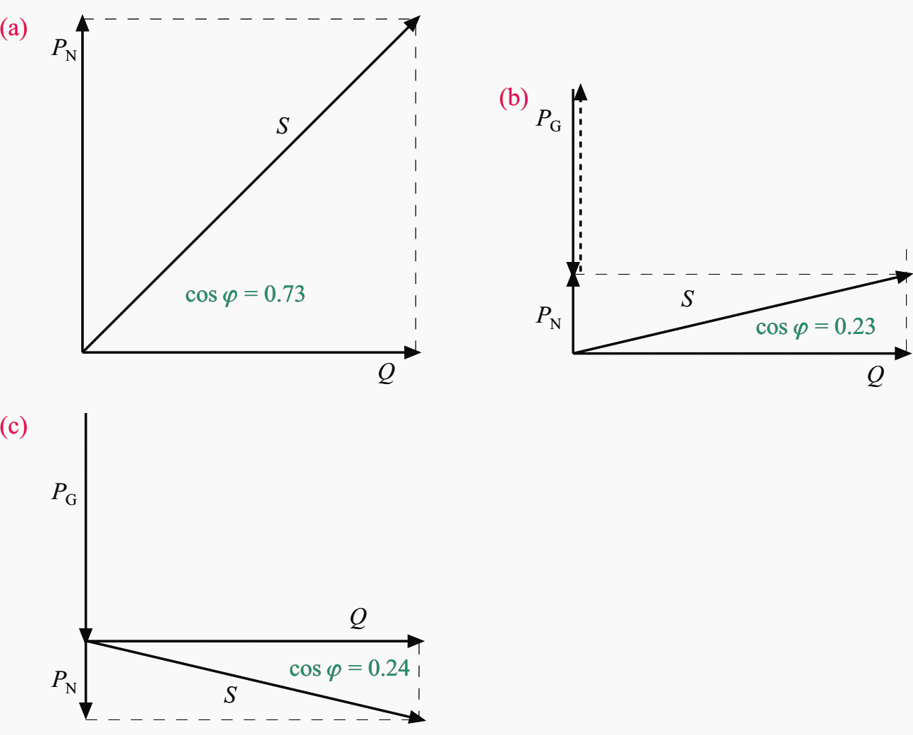
Even though a generator is running in parallel just to reduce the consumption of the active energy from the main supply, the vectors are still moving within the first or second quadrant only (see Figure 2b).
However, if the generator takes over the complete active power consumption and even feeds back active energy into the electricity supplier’s grid, then the vectors change into the third or fourth quadrant (see Figure 2c).
Thus the controller indicates any possible value within 360° of the coordinate system, provided that it is suitable for four-quadrant operation. This is the pre-supposition that the reactive power controller is applicable for operation within all four quadrants.
It must be underlined again that the actual power factor cos φa does not say anything about the actual amount of reactive power Q.
Vector 4 in quadrant IV in Figure 1 symbolizes the load situation where the generator is covering the consumption of active power totally and is feeding back an identical amount to the grid in addition. If the target power factor had been preset to 0.85 lagging, the controller would suddenly intend to compensate to the 0.85 leading side!
The C/k bandwidth is extended from the first quadrant via zero into the third quadrant. This is called the mirror-imaging behaviour of the controller.
It does not ensure that the compensation bank will be sufficient to compensate according to the 0.85 leading side (see vector 6). Seven capacitor steps would become necessary in order to achieve this power factor target.
To get proper control of reactive power does not mean presetting the power factor target into the second quadrant, for example the 0.9 leading side in order to achieve the 0.9 lagging side when controlling in the fourth quadrant (see Figure 1).
The simplest way to solve this problem is to preset the power factor target to unity, cos φd = 1. With this power factor target, symmetrical control of reactive power is ensured within all four quadrants (see vectors 5 and 2). Thus if the reactive power compensation is working within all four quadrants the capacitors’ capacitance is determined sufficiently in order to achieve an average power factor of unity, cos φ = 1.
Remember that the total compensation of reactive power saves active energy (kWh) due to power losses along the leads. This solution is indispensible not only from a technical viewpoint, but also from the economical side as well, as described in the next section.
Go back to Table of Contents ↑
2.2 Bargaining Considerations
As mentioned above, customers with their own generator(s) are obliged to compensate reactive power to a desired power factor much closer to unity, cos φd = 1.
Any standard tariff agreement on achieving an average power factor of 0.9 for instance becomes invalid. This standardized contract agrees that 48.5% of the consumption of active energy is free of charge with respect to the amount of reactive energy. In simple terms, if the consumption of active energy amounts to, for example, 1000 kWh per billing period, then 485 kvarh of reactive energy is free of charge.
As a matter of course the electricity company will not grant any kvarh without charging. Many electrical plants with generators are using asynchronous generators, that is asynchronous motors running with so-called negative ‘slip’. Independent of whether the engine is running in motor or generator mode, it consumes reactive energy for magnetizing the iron core steadily.
Thus each customer intending to reduce the consumption of active energy particularly or even totally by the generator(s) is obliged to compensate any reactive energy totally as well, except if the customer has negotiated a special contract with the electricity utility company.
The following example underlines the facts described above.
Go back to Table of Contents ↑
2.3 Example
An asynchronous motor of 100 kVA rated power is to be driven in generator mode. Its nominal power factor is 0.82 inductive. Although it is feeding back active energy into the grid, the consumption of reactive power amounts to:
cos φ = 0.82 ⇒ φ = 34.9° ⇒ sin φ = 0.572
The reactive power of the generator is to be calculated by:
Q = S × sin φ = 100 kVA × 0.572 = 57.2 kvar
In operating with synchronous generators the consumption of reactive energy depends on the preset exciting rate. They are preset to a power factor referring regularly to the lagging side. Then the reactive power of the generator is calculated in the same way as for the asynchronous one.
Go back to Table of Contents ↑
3. Conclusions
Compensating reactive power within all four quadrants of the coordinate system due to generators running in parallel requires consideration of technical and economic facts in totally another way to that known from classical two-quadrant operation.
It is a matter of course that the controller’s current transformer must ‘seize’ the reactive current of the generator(s) as well. Thus the feed-in point of the generator(s) always has to ‘look’ to the L side of the current transformer’s casing.
Individual, national or international instructions are to be followed.
Go back to Table of Contents ↑
Source: Reactive power compensation by Wolfgang H., Jurgen S. and Wolfgang J.
Related electrical guides & articles


Edvard Csanyi
Hi, I'm an electrical engineer, programmer and founder of EEP - Electrical Engineering Portal. I worked twelve years at Schneider Electric in the position of technical support for low- and medium-voltage projects and the design of busbar trunking systems.I'm highly specialized in the design of LV/MV switchgear and low-voltage, high-power busbar trunking (<6300A) in substations, commercial buildings and industry facilities. I'm also a professional in AutoCAD programming.
Profile: Edvard Csanyi

thank you for the precious information,this is not the first time i read subjects written by you sir,so thanks very much.
my question :is how to manage and control reactive power in synchronous generators operating in parallel isolated from grid in island mode,especially dissimilar synchronous generators,which are not similar in rating and from different manufacturrers ,this applies also to the load sharing modules,iknow its difficult,but you as an expert may have asolution.
also i found in some sites that active power sharing between dissimalar synch.gen may be easy but plc control is needed in case of reactive power…..thank you
Thanhks so much!