
Estimated Study Time: 20 minutes
Why reactive power and PF correction?
Why reactive power and power factor correction are so important? Well, for experienced engineers, this is not the question but the fact. For young students who meet this matter and terms for the first time, it’s important to explain the matter very carefully, because much future knowledge will be built on its basis.
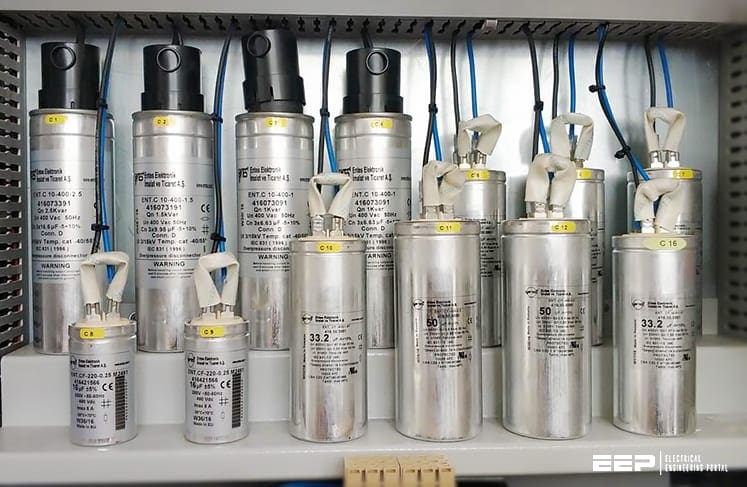 Reactive power and power factor correction essentials to ALWAYS keep on mind (on photo: Low voltage capacitors installed in an enclosure to improve power factor)
Introduction to terms
In AC circuits, the current absorbed by a load can be represented by two components: active component IR and reactive component IQ.
The active component IR, in phase with the supply voltage, is directly related to the output (and therefore to the part of electric energy converted into energy of different types: mechanical energy, light energy, thermal energy…);
The reactive component IQ, in quadrature to the voltage, is used to generate the flow necessary for the conversion of powers through the electric or magnetic field and it is index of the transfer of energy between supply and load. Without this, there could be no net transfer of power, for example, thanks to the magnetic coupling in the core of a transformer or in the air gap of a motor.
In the most common case, in the presence of ohmic-inductive type loads, the total current I lags with respect to the active component IR. Therefore, in an electrical installation, it is necessary to generate and transmit, in addition to the active power P, a certain reactive power Q, which is essential for the conversion of the electrical energy but is not available to the load because exchanged with the network.
The complex of the power generated and transmitted constitutes the apparent power S. Power factor cosϕ is defined as the ratio between the active component IR and the total value of the current I; Φ is the phase angle between the voltage and the current.
In this way, the lines, the generators and the transformers can be sized for a lower apparent power, as better explained in the following paragraphs.
- Reactive power and its effects
- The effects of low power factor
- Power Factor Correction
- Power Factor improvement at the load
- Capacitor Installations
- Energy Saving Costs using PFC
1. Reactive power and its effects
The necessary presence of reactive elements in AC circuits and the associated requirements of reactive power or VARs to service these elements cause significant problems in the operation of such AC supply systems.
The net reactive power requirements must be met by the source and this can have significant impact on the operation if some steps are not taken to alleviate the problem.
S = P + jQ = V × I* (where I* is the complex conjugate of I)
We define the reactive power to be positive when it is absorbed (as in a lagging power factor circuit).
a. Pure capacitance element – For a pure capacitance element, P=0 and I leads V by 90° so that complex power is:
S = jQ = (V ∠0°) (I ∠90°)
S = V×I ∠−90°
S = −jV×I
Thus the capacitance element generates reactive power.
b. Inductive element – Similarly, for an inductive element, P = 0 and I lags V by 90° so that:
S = jQ = (V ∠0°) (I ∠−90°)
S = V×I ∠+90°
S = +jV×I
Thus the inductance element absorbs reactive power. Most loads are net inductive and so they require reactive power to be supplied by the source. Similarly overhead lines are net absorbers of reactive power, but cables, with their high capacitance are net generators of reactive power and this has to be handled by the source.
The presence of reactive power in a load means that the power factor is reduced from unity and so it is best to operate at high power factor.
For a general (lagging) power factor cosΦ , the current lags the voltage by Φ, while for a leading power factor the current leads the voltage by Φ. The various phase relationships and the corresponding phasor diagrams are shown below.
Lagging circuit:
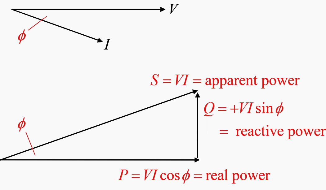
Leading circuit:

Note that (the convention says) reactive power is positive (absorbed) in lagging power factor circuits and is negative (generated) in leading power factor circuits.
Note also that:
Total Current |I| = √((I cosφ)2 + (I sinφ)2)
Apparent power |S| = √(P2 + Q2) = √((VI cosφ)2 + (VI sinφ)2)
2. The effects of low power factor
There are two main problems associated with low power factor (or the presence of reactive power) in a load:
- Voltage drop
- Efficiency (and cost of energy supply)
2.1 Voltage Drop
The reactive component of current, I × sinφ , causes unwanted voltage drop that affects the regulation at the load.

2.2 Efficiency and cost
The reactive current (I sinφ ) also generates additional heat loss in the connecting lines and for this reason the supplier will impose limits on the load power factor by imposing an additional cost premium on low power factor loads.
3. Power Factor Correction
The traditional means of correcting power factor for the typical lagging circuit is by installing capacitance to generate some of the reactive power required by the load so as to remove the necessity of the supply from providing it.
There are two configurations available for capacitance installation: series and shunt connection.
3.1 Series Connection

In the diagram below, Vs‘ is the source voltage without capacitance and Vs is the source voltage with capacitance correction.

The voltage regulation is:
ΔV = |VS| − |VR|
Thus the added VAR generation is QC = I2 XC and the resulting improvement (decrease) in the voltage regulation is: QC sinΦ / I volts
Series connection has some advantages and disadvantages:
- The reduction in total I is small so that the improvement in loss in the line is very small.
- Series capacitance is very good for voltage regulation and for improving (smoothing) voltage fluctuations.
- The series capacitance helps to improve stability if the line reactance is high.
- Series connection is much less flexible than shunt connection in that the capacitance value is not easily able to be changed.
3.2 Shunt Connection of Capacitance

Note that:
I’ = IR + IC
QC = VR IC

Regulation in this case is:
ΔV = IRRcosΦ + IRXLsinΦ − ICXL
And the voltage boost is:
ICXL = QCXL / VR
The advantages and disadvantages of shunt connection are:
- Improves power factor and reduces line current significantly and thus reduces line losses significantly.
- Not as good as series connection for voltage smoothing.
- Has much greater flexibility of use than series as change of the value has no effect on load current.
In general, series connection is rarely used, except in some very high voltage long transmission lines where better voltage regulation is needed.
The use of shunt capacitors is almost universal for distribution systems and loads, where the flexibility of shunt connection allows automatic compensation using switched capacitor banks (static VAR compensators) that can adapt to changing load conditions.
Important Note:
In the above, the discussion has been for lagging power factor loads, the most common type. For leading power factor loads it is necessary to add in some means of absorbing reactive power such as series inductance.
Alternatively, an option used on some transmission lines is the use of unloaded synchronous motors at the load end of the line:
- When over-excited the synchronous motor will operate at leading power factor and generate VARs
- When under-excited the motor will operate at lagging power factor and absorb VARs.
4. Power Factor improvement at the load
The improvement of power factor at the consumers load will improve voltage regulation and the power transfer efficiency.
The basic aim is to increase cosΦ (typically 0.55-0.8) to some higher value cosΦ’ (typically about 0.9-0.95).

This will reduce the current magnitude from I to I’ and hence the line losses from I2R to I’2R. Similarly, the reactive current component IQ will reduce to IQ‘ , where:
IC = IQ − IQ‘
This can be achieved in either of two ways, depending on load requirements:
- At constant total real power (P): This is done by reducing the total line current for the same total load P.
- At constant total apparent power (S): This is done by allowing the same total line current but increasing the total real power (P) at the load.
4.1 Correction at constant real power

|S1| = VI1
|S2| = VI2
P = VI1 cosΦ1 = VI2 cosΦ2
Q1 = VI1 sinΦ1
Q2 = VI2 sinΦ2
We need installed capacitance C to generate reactive power of Q1 − Q2 VARs. Thus we need:
ΔQ = Q1 − Q2 = P (tanΦ1 − tanΦ2)
For shunt capacitance:
ΔQ = IC2XC = VC2 / XC = ωCVC2
The reduction in line current is:
I2 = I1 × cosΦ1 / cosΦ2
For example, for cosΦ1 = 0.65 and cosΦ1 = 0.90,
I2 = 0.72 I1 [a reduction of 28%]
I2 = 0.52 I12 [a reduction of 48%]
4.2 Correction at constant S
This method increases availability of real power for possible increase of load capacity for a fixed source current.

Initially, at cosΦ1, power P1 is available:
P1 = S cosΦ1
Q1 =S sinΦ1
After correction, at cosΦ2, P2 is available:
P2 = S cosΦ2
Q2 = S sinΦ2
To achieve this we require reactive power generation: ΔQ = S(sinΦ1 − sinΦ2)
5. Capacitor Installations
PFC installations (Static VAR Compensators or SVCs) are extensively used in transmission and distribution systems and in industry and commercial buildings where reactive power may be high. The capacitors are installed in banks made up in modular and separately switchable units which can range from 7.5kVAR to 100kVAR or higher.
Automatic power factor sensing is used and appropriate capacitance values are switched in and out as required, usually by thyristor switches.
Synchronous motor compensation is mostly used on transmission systems (when it is used).
6. Energy Saving Costs using PFC
Most items of large and extensive distributed equipment operate at relatively low power factors and thus benefit from power factor correction. To determine the benefit requires some study of the cost-benefit analysis of such capacitor installations.
Table 1 – Typical power factors
| Source | Power factor |
| Incandescent loads | 1.0 |
| Heating loads | 0.95-1.0 |
| Fluorescent lighting | 0.6 (about 0.95-0.97 when individually corrected) |
| Large induction motors | 0.75-0.9 at full load |
| Small induction motors | 0.6-0.85 at full load (fractional horsepower size) |
6.1 Energy Metering and charging methods
Small consumers of electrical energy pay for their power by the individual kilowatthour (kWh) usage. There is no significant benefit from power factor improvement for small consumers.
For large users of energy, such as industry and commerce and similar establishments, the method of assessing charge may be one of a number of options. These are all based on a capacity charge basis where the peak demand is monitored and is used to assess the charge.
They may be:
- A daily capacity rate per kW peak ($/kW/day)
- A daily capacity rate per kVA peak ($/kVA/day)
Note that whenever kVA or kVARs are used as the charge basis there is some potential for cost reduction by installing capacitors banks, or installations of VARs.
Typically, the cost of capacitors may be about $20-$40 per kVAR. This cost must be used with the amortized saving to determine the potential economic benefit. Normally a cost recovery time of a year or so would be aimed for. Any longer time would not be considered adequate benefit, although the added bonus of reduction of line losses should be included.
6.2 Loss Reduction
The other savings benefit that comes with power factor correction occurs with the reduction of losses in the feeder connections. The per unit reduction in ohmic (I2R ) loss due to reduction of line current is:
P U loss reduction = 1 − (PFold / PFnew)2
Typically, line losses are about 3–7% of total load power usage. Any reduction of the 3–7% will give substantial benefit if the load power consumption is high.
Example:
A 1000 kW load is operated for 60 hours per week from a 415V supply with 7% loss in the supply lines. The load PF is 0.75 and the energy charge is $0.10 per kWh. What are the cost benefits of increasing PF to 0.95?
If the load power factor is increased to 0.95, the loss improvement is:
1 − (0.75 / 0.95)2 = 0.377 = 37.7%
Thus the new losses are 0.623 × 7% = 4.36 %
Old kWh loss per week was: 0.07 × 1000 × 60 = 4200 kWh
Energy cost was 4200 × $0.1 = $420 per week
New kWh loss per week: 0.0436 × 1000 × 60 = 2618 kWh
Energy cost is now (2618) × $0.1 = $261.8 per week
Saving is 420 – 261.8 = $158.2 per week or $8,226 per annum. [$685.5 /month]
For PF = 0.75, S = 1333 kVA, Q = 882 kVAR
For PF = 0.95, S = 1053 kVA, Q = 329 kVAR
Thus, need 882 − 329 = 553 kVAR of installed capacitance. If the cost of the capacitors is $20/kVAR, installation cost is $11,060. Time to achieve cost recovery is 11,060 / 686 = 16.1 months.
6.3 Inrush current
In addition to the harmonics problem, use of capacitor banks will also cause transient HF inrush currents when they are energized. These may cause some problems.
For a capacitor installation with reactance XC, installed in shunt where there is inductive reactance XL between the capacitor and the source, the inrush current is:

and frequency is:

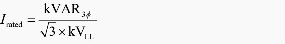
Shunt capacitors are protected by fuses. Fuse links are usually sized at 125% to 135% of the rated capacitor current. This is to allow for overvoltage conditions, transient currents, harmonic. The rated current for a 3-phase capacitor bank is:
Sources:
- Reactive Power and Power Factor Correction Lecture
- Power factor correction and harmonic filtering in electrical plants by ABB
Related electrical guides & articles


Edvard Csanyi
Hi, I'm an electrical engineer, programmer and founder of EEP - Electrical Engineering Portal. I worked twelve years at Schneider Electric in the position of technical support for low- and medium-voltage projects and the design of busbar trunking systems.I'm highly specialized in the design of LV/MV switchgear and low-voltage, high-power busbar trunking (<6300A) in substations, commercial buildings and industry facilities. I'm also a professional in AutoCAD programming.
Profile: Edvard Csanyi

Am test engineer for Solar inverter and to test our inverter we use Inverter back to back,one inverter work as converter and other in Inverter mode,where the Losses supplied by a DC sources and both converter and Inverter are isolated with isolattion transformer
Recently test rig was upgraded with 7.5MVA Transformer, but transformer kept away from 100 meters away due to oil type transformer,this is connected with bus duct 7000A rated,now we measure lot of reactive component added due to the bus duct,Please give your thought to make it PF-1, is the only way to add capacitors in the network
Is it necessary to correct power factor in hydropower plant. If yes; on what condition and at what locations?
What device are you using, an induction generator? If so is it grid tied? IG’s produce power with a leading PF. This means the usual method of adding capacitance won’t work.
how to detect harmonics and whats the remedy to overcome it .I am going to install capacitor bank at stone crusher plant which has induction motors with dol and star Delta starter no vfds there .will it cause harmonics
capacitor banks are enough ??
Knowledge is power….
Very informative indeed. Thank you!
Very valuable information
In above calculation you are using the value of 0.623 and 0.436. I want know how they are getting and why. please inform me.
With regardas
Hanamantraya
Owesom
Valuable material.
nice article specially for the students.. but why i cant Save to PDF.. i am a premium member. thank you
Kind of confuse with meter billing methods as regards instrumentation and calibration if the energy meters mostly in kwh..
My question is how can a power factor correction be done on billings or meter readings in kwh…when no p.f or reactive componenet was not measured/bill…