
Estimated Study Time: 20 minutes
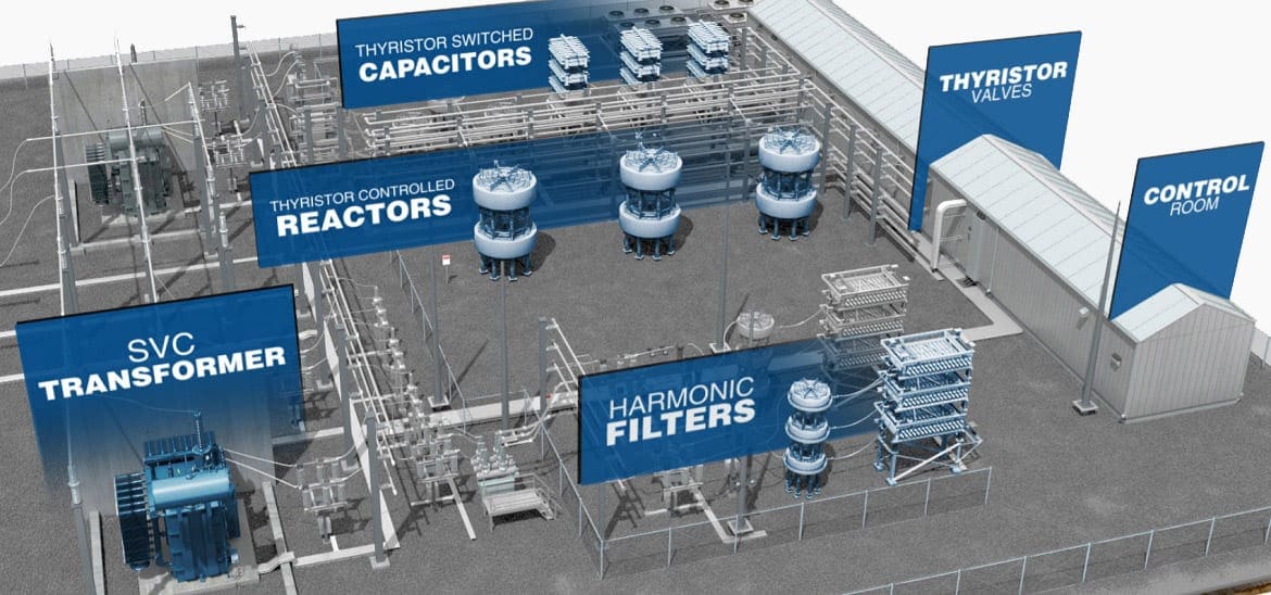
Reactive power (VAr) compensators
To be honest, transmission and distribution networks are full of problems. But that’s nothing new, and you already knew that. This technical article will shed some light on solving some pretty severe problems in transmission and distribution networks by using reactive power (VAr) compensators.
 Troubleshooting electricity T&D network with reactive power (VAr) compensation
The voltage drop in an AC electric power supply system, caused by problem loads which are large compared with the short circuit level of the system, is mainly due to reactive component of the load flowing through the system reactance.
The variations in loads can cause voltage fluctuations and consequent objectionable or irritating light flicker. These troublesome loads sometimes produce harmonic currents, which are large enough to cause distortion problems to other consumers whose electricity supply is provided from the same busbar (the point of common coupling).
To provide reactive VAr control in order to support the power supply system voltage and to filter the harmonic currents in accordance with Electricity Authority recommendations, which prescribe the permissible voltage fluctuations and harmonic distortions, reactive power (VAr) compensators are required.
The speed of response of the synchronous compensator is low and the cost is high when compared with the static VAr compensators and hence the latter are the preferred solution.
1. What Is Static Var Compensator?
Static var compensator (SVC) is a shunt connected static var generator or absorber whose output is adjusted to exchange capacitive or inductive current to maintain or control specific parameters of the electrical power system (typically bus voltage).
Static var compensator system provides dynamic reactive power and is directly connected to the bus of an electric appliance. Maximum SVC’s reactive power is generated by capacitors of harmonic filters and is equal to maximum reactive power of the appliance.
Response time of the SVC control system to changes of controlled parameters is 5 ms for EAF and 25-100 ms for general industrial applications and transformer substations.
SVC control and protection system allows unmanned operation of the equipment. Rated power and combination SVC device components are defined for particular projects depending on parameters of the power supply system as well as type and power of compensated load.
At least four different types of static Var compensator (SVC) are available. These are:
- Saturated reactor type compensators,
- Thyristor controlled reactor compensator,
- Thyristor switched capacitor compensator and
- STATCOM (Static Compensator).
1.1 Saturated Reactor Type Compensator
The Power Transmission Division of GEC, Stafford, was the pioneer of saturated reactor type compensator. The saturated reactor type compensators were first developed in the 1960’s by AREVA (then GEC) under the guidance of Dr. E. Friedlander. These are transformer type devices, which were built in the factory of AREVA (then GEC) Transformers Limited in Stafford.
It does so by the nature of the saturation feature of the magnetising characteristic of its core iron as it operates normally in saturated flux region. The saturated reactor is inherent in its response and the speed of response is fast. The reactive power required for compensation is generated by parallel connected shunt capacitance (often in the form of tuned or damped harmonic filters).
The order of harmonic filters depends primarily on the harmonic (number) currents generated by the troublesome loads. There are different types of saturated reactors, namely twin tripler reactor, treble tripler reactor and tapped reactor.
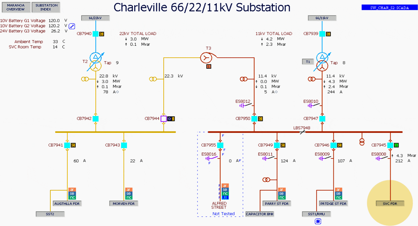
Example of Saturated Reactor Type Compensator
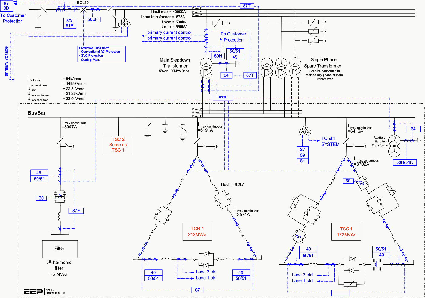
The SVC installed in Substation ‘Charleville‘ performs the function of maintaining stable voltages at both high and low load times. At low load times, without the SVC in service, significant voltage rise would occur on the Charleville area network.
Similarly, without the SVC’s capacitive support, voltage would become low during high load periods.
At peak load times, without the SVC in service, some loads may also need to be shed in order to maintain a suitable voltage.
Figure 3 above provides an overview of Charleville substation basic configuration.
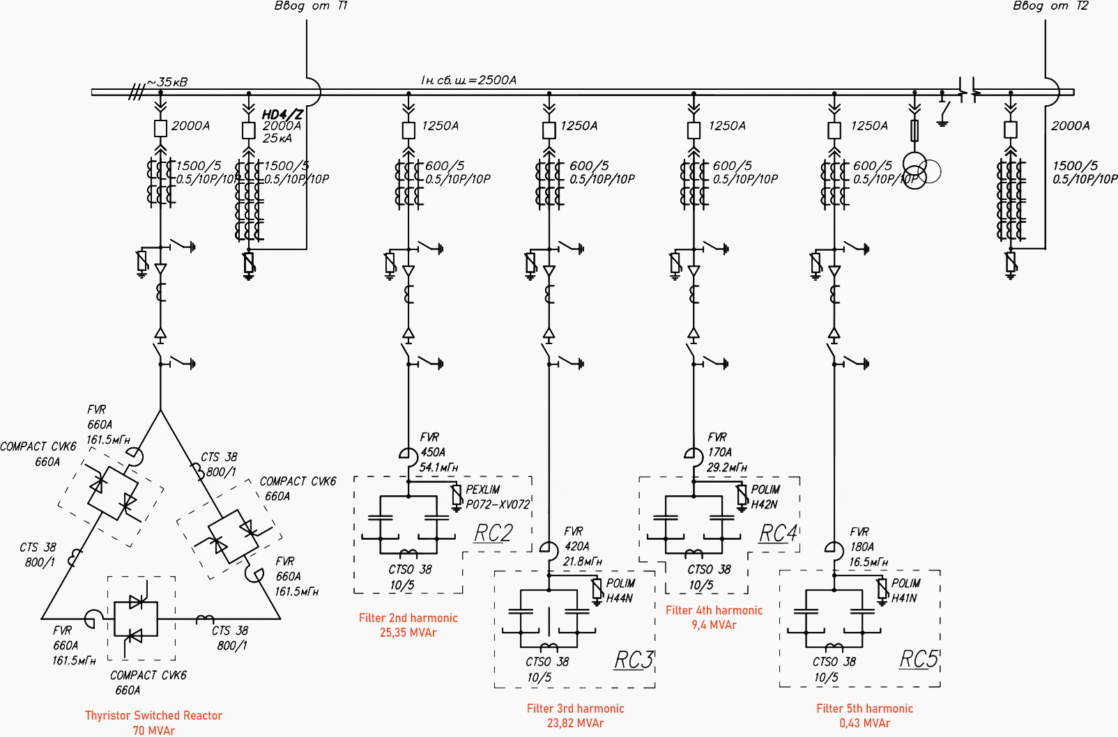
1.2 Thyristor Controlled Reactor Compensator (TCR)
Thyristor controlled reactor (TCR) is a shunt connected thyristor controlled inductor whose effective reactance is varied in a continuous manner by partial conduction of the thyristor valve. The thyristor controlled reactor comprises a linear reactor, connected in series with a ‘thyristor valve’ made up of inverse-parallel (back-to-back) connected pairs of high power, high voltage thyristors.
In saturated reactor the current is ‘switched’ by core saturation. In a TCR the current is switched by thyristors. As in the case of a saturated reactor compensator, the reactor power required by the loads is generated by parallel connected shunt capacitance (as mentioned above, often in the form of harmonic filters).
During system light load conditions, the excess reactive power from this shunt capacitance is absorbed by thyristor controlled reactor. The design of the harmonic filters depends on the harmonic generated by both the thyristor compensator and the problem loads.
The major harmonic frequencies which the TCR produces in the AC supply depend on the pulse number p, (e.g. p = 6) in accordance with the formula h = kp + 1 where h stands for the harmonic number and k is a positive integer.
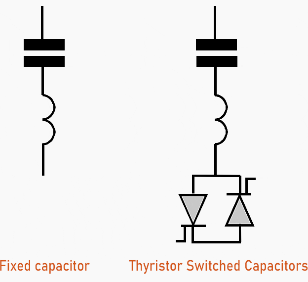
1.3 Thyristor Switched Capacitors (TSC)
Thyristor switched capacitor (TSC) is a shunt connected thyristor switched capacitor whose effective reactance is varied in a stepwise manner by full or zero conduction operation of the thyristor valve.
Thyristor valves consisting of inverse-parallel connected thyristors, generally similar to those used for the TCR, are used to give rapid switching of blocks of capacitors.
The decay of the stored charge takes several minutes and this imposes a doubled voltage stress on the non-conducting thyristor and an increase is necessary in the number of thyristors in series in a TSB.
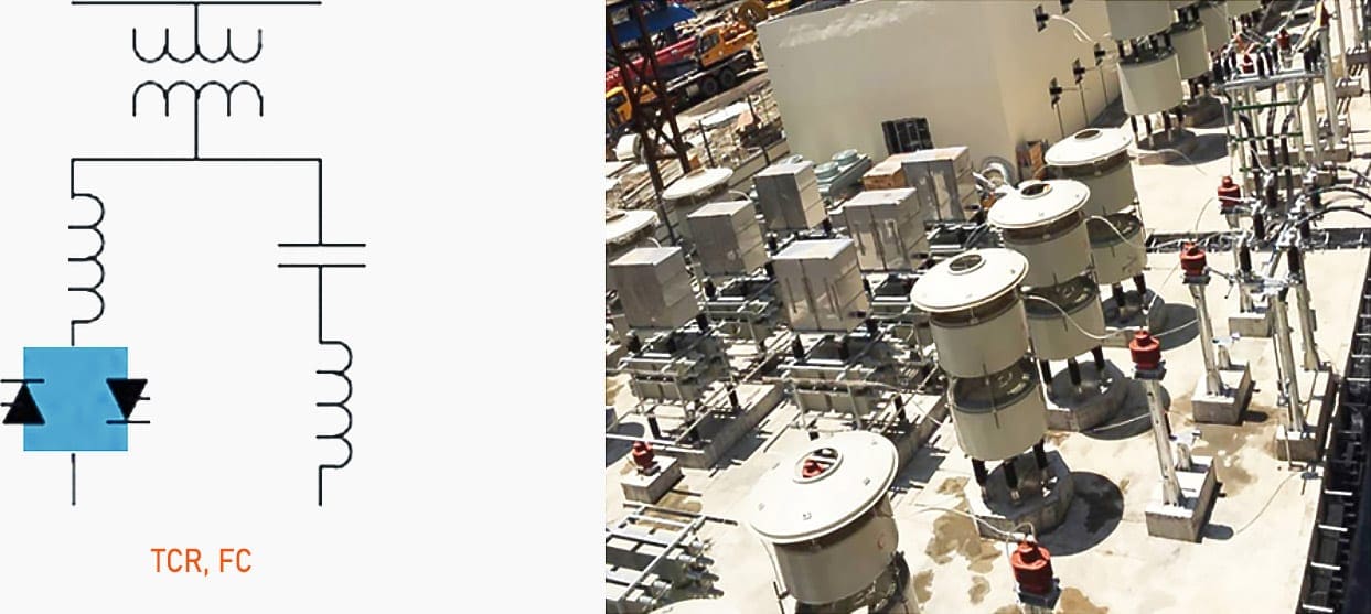
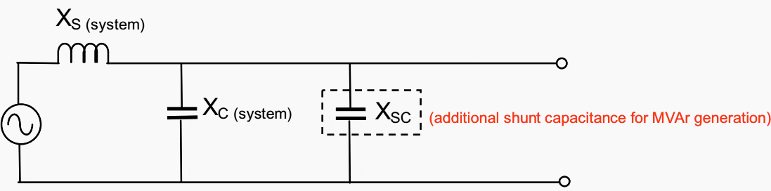
1.4 Static VAr Compensator
The general arrangement of the Static VAr Compensator is shown in the diagram below. It consists of thyristor controlled reactors (TCR) in parallel with thyristor switched capacitors (TSC). The reactive equipment of the compensator are connected to the transmission line, through a transformer to prevent the equipment having to withstand full system voltage.
A control system determines the exact gating instants of reactors according to predetermined strategy. The strategy usually aims to maintain the transmission line voltage at a fixed level.
The continuous variation in the TCR is used in combination with the stepped effect of switching in or out integral capacitor units in the TSC to achieve an effective continuous variation of reactive power over the whole operating range.
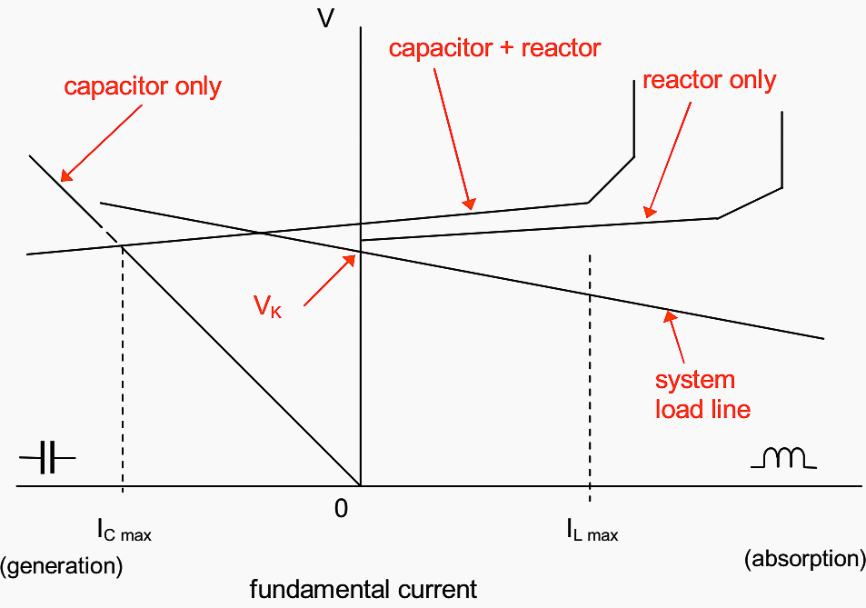
The typical characteristics of the combined TCR and TSC, the static VAr compensator (SVC) are shown in the Figure 6.
Static VAr compensators are used to help power transmission over long AC transmission lines by injecting reactive power at points down the line to maintain voltage levels. The Figure 7 shows the typical characteristic of the combined compensator.
This arrangement is now capable of providing a range of leading and lagging reactive power support to its operating voltage.
1.5 STATCOM (Static Compensator)
A static synchronous generator operated as a shunt connected static VAr compensator (SVC) whose capacitive or inductive output current can be controlled independently of the AC system voltage. STATCOM is based on a voltage source converter.
STATCOM has superior dynamic reactive power compensation ability and wider operating voltage range, than a normal SVC.
The phases of the STATCOM are independently controlled during system disturbances.
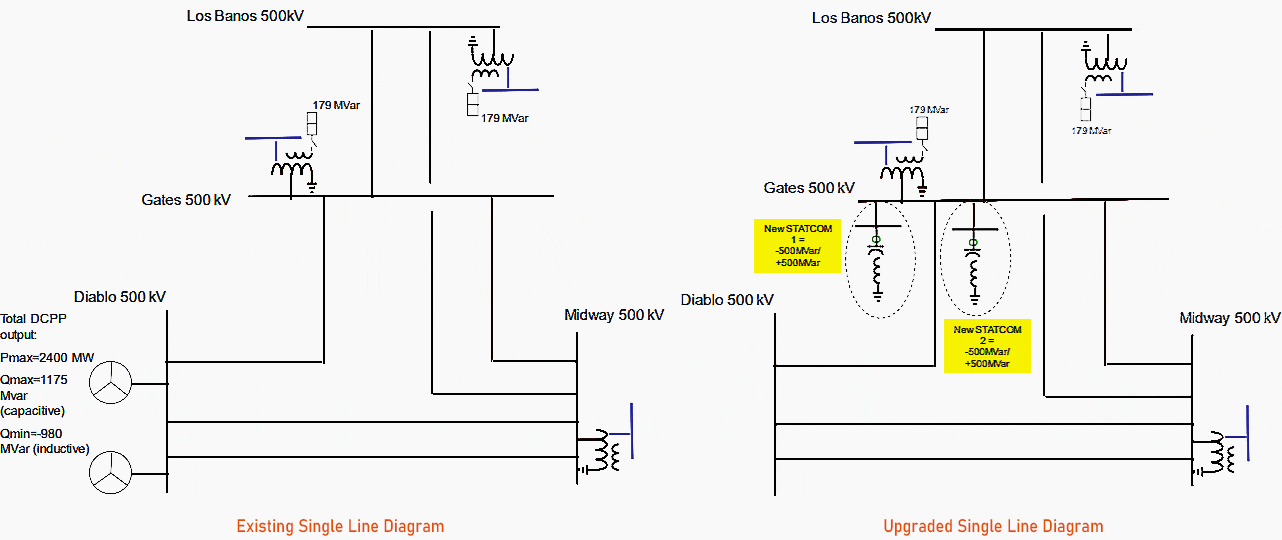
Above single line diagrams represent PG&E’s single line diagram of existing transmission project and proposal for upgrade with installation of two +/- 500 MVAR STATCOM segments providing a total of 1000 MVARs capacitive and 1000 MVARs inductive reactive support with continuous and controlled capability.
Both STATCOMS could operate independently, providing redundancy and provide dynamic support to the grid even when one is out of service.
2. Problem Loads
2.1 Arc Furnaces
Arc furnaces are electrothermal devices used to manufacture steel. Furnaces of this type are mainly used for obtaining steel from recycled scrap. Many types of arc furnaces for melting steel are used. The three-phase Heroulte arc furnaces are the most popular in the world.
In 1996, 31% steel was produced in arc furnaces and 39% in 2007. It is planned that in 2030, more than 50% of steel will be produced in arc furnaces. Along with the development of the steelmaking industry, there were also changes in the construction of furnaces. The average melting time has been reduced from 4-6 hours in first generation furnaces to 50-60 minutes – fourth generation.
Therefore, arc furnaces for most of the time of melting cause interference in the supply network.
2.2 Electric Welding
There are a wide variety of applications for electric welding. The method used can broadly be divided into arc welding and resistance welding. The control of the welding in both cases can be automatic or manual. Welding is mostly controlled by thyristor control.
Flicker occurs when a variable load such as a welding machine or crane demands a high current in a very short period of time
Typically, flicker is observed by dimming lights. But it can have serious effects on a wide range of sensitive equipment, especially PLCs and computers.
2.3 Mine Winders
Mining activities involve challenging electrical loads. While large crushers, shredders, conveyors and SAG & BALL mills combine enormous requirements for power with very dynamic behavior, other devices such as winders and ventilation systems require stability for their continious operation.
Moreover, in many situations mining installations are located at the edge of the power grid with long distances, up to hundreds of kilometers from the closest power generation plant.
Mine winders (e.g. in the coal industry) are driven by thyristor-fed DC drive motors. The duty imposed on the AC power supply system is severe due to the varying power demand of the DC drives. Every time a winder accelerates it demands a very high amount of reactive power from the system.
Because of the thyristor-fed drive, it also generates harmonic currents which need filtering.
2.4 Rolling Mills
Rolling mills are driven by DC motors fed from thyristor converters. Every time the rolls reverse a large change in reactive power demand occurs in a few cycles. This change in reactive power demand occurs in a short period during acceleration.
When compared to an arc furnace, however, overall duty on the power supply system is less severe (as in the case of mine winders) both because the rate of change is slower and the load in the three phases is balanced.
2.5 Shunt Capacitor Bank
Shunt capacitor banks are mainly installed to provide capacitive reactive compensation / power factor correction. Because they are relatively inexpensive, the use of capacitor banks has increased. Shunt capacitor banks are composed of capacitor units mounted on the racks.
They can be easily and quickly installed virtually anywhere in the network. Its installation has beneficial effects on the system such as improvement of the voltage at the load, better voltage regulation and reduction of losses.
Mechanically switched capacitor bank (shunt connected) may be installed on transformer tertiaries or connected directly to 132kV, 275kV, 400kV, 500kV or higher grid system.
In the case of back-to-back switching of Mechanically Switched Capacitor banks, these shunt capacitor banks are to be connected to grid system via damping reactors (in series with capacitor banks).
Sources:
- Substation design application by Ayadurai V.
- Industrial Static Var Compensators by ČKD ELEKTROTECHNIKA
- PG&E’s 2018 Request Window Proposals CAISO 2018-2019 Transmission Planning Process
- The Influence of Disturbances Generated by Arc Furnaces on the Power Quality by Z. Olczykowski
- Power Quality Success Story – Better weld quality, lower power consumption – and not a flicker by ABB
Related electrical guides & articles


Edvard Csanyi
Hi, I'm an electrical engineer, programmer and founder of EEP - Electrical Engineering Portal. I worked twelve years at Schneider Electric in the position of technical support for low- and medium-voltage projects and the design of busbar trunking systems.I'm highly specialized in the design of LV/MV switchgear and low-voltage, high-power busbar trunking (<6300A) in substations, commercial buildings and industry facilities. I'm also a professional in AutoCAD programming.
Profile: Edvard Csanyi

i have been got nice concept
but how can i test dc voltage on solar farm?
Amazing work
Thanks for this very vital part of power system.
Very good informative artical on Reactive Power and Voltage Control, Regard, Riaz Abbasi
I am fortunate enough to work on several SVC systems and also sepcify and supervise a new SVC system installation. SVC on arc furnace applications, apart from controlling power factor, it is also designed to control comination of parameters such as, voltage imbalance, harmonics and flicker.
Working in the cathodic protection industry we find a lot of issues of stray voltages related to “grounded neutral” paths that take cathodic protection to power grounding elements, robbing protective current from the facilities intended to receive cathodic protective current. We have also seen issues from the use of power line capacitors and local industrial use power factor capacitors – especially when one or more of the capacitors has failed. Is there any training or information available to help the cathodic protection industries with these stray current path mitigations?
Hi Edward,
From the article (last section) it appears that Shunt Capacitor Banks are a “load problem, since this topic was placed in chapter 2, section 2.5.
Would you be so kind to elaborate on the problem, please.
Kindest regards.
Shunt capacitor banks are used in networks to solve the load problem concerning a low power factor. They provide capacitive reactive compensation – power factor correction.
Thank you for sharing these very interesting information
Dear Mr. Muhammad Jawad,
Related to ETAP software I can teach you how to use it for all your needs.
I am an authorized instructor from the ETAP certified Representative for Venezuela.
If you are interested in know more details, please contact me at [email protected] or call at +58 414 912 7604,
Sincerely,
Chakib Abi-Saab Soto
CARACAS, VENEZUELA
Dear Mr. Edvard Csanyi,
It was a pleasure to read your very good work on the subject of Controlling power system parameters through reactive power (VAr) compensation.
it is very clear and informative and I appreciate the time and effort you expended on collecting, resuming and writing this article.
thank you very much
Thank you for sharing and indeed very informative.
Do you have any Article on how to perform power system studies? Please share
Thank You for this well written article. It was very informative.
I always learn new things from your portal. Can you please guide me on how I can learn Etap software. I wish to use it inpractical low voltage system that for commercial and highrise builings supply. Also how can I get licensed Etab.
I live in a developing country at what stage can these compensators be installed in electrical network substations because l have not come across them.
Topic well covered for substations