
Estimated Study Time: 39 minutes
Tripping, disconnector, ground-switch…
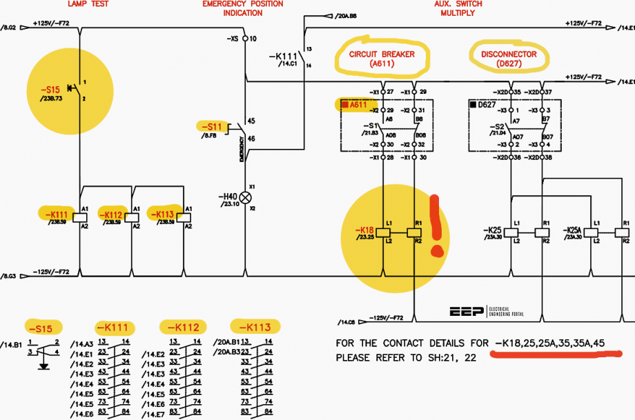
The single-line diagram example for a double-bus and a single breaker clarifies several concepts that are for the GIS only. It is challenging to comprehend and grasp the control circuits due to the interrelated components and functions that impose additional interlock schemes and control functions.
 Learn how to read and analyze control circuits of MV gas insulated switchgear (GIS)
Previously, an introductory part of the GIS and its components were discussed to pave the way for the GIS control circuits (read the article).
Hence, a brief description of drawing tips and drawing examples are elaborated before delving into the actual article topics (control circuits). Broadly, control circuits are categorized into:
- AC & DC auxiliary circuits
- DC of secondary (close/trip) for CB, disconnector, and ground switches
- Indication and alarm circuits
- SCADA indication and alarm circuits
- Equipment coil contacts arrangements and components details
- AC of secondary (CT & PT)
The first group shares similar concepts with the MV switchgear circuits in previous articles, so they were mentioned briefly. The second group includes many circuits-namely, breaker closing circuit, breaker trip circuit, and disconnector/ground switch close/open circuit. The breaker closing circuit requires so many conditions fulfillment before closing.
As a result, it is expected to have a complex circuit as we experienced in the last article.
Of course, the MV switchgear two articles are to be covered first for easier understanding. You can consider it as a series of articles that tackle the MV switchgear and then move to the GIS, so the difficulty level increases steadily. However, once you master it, it becomes an invaluable tool for your practical expertise for design, maintenance, and troubleshooting.
- Circuit Breaker Tripping Circuit
- Disconnector/Ground Switch
- Bay Control-Protection Unit (BCPU) and Alarm Circuit
- Secondary AC Circuits
- Summary
1. Circuit Breaker Tripping Circuit
In the previous article, there was a general closing command that must be pressed along with the breaker selector pushbutton to close the breaker in the emergency mode so that any accidental activation of the breaker selector pushbutton does not result in a breaker close.
The same philosophy is implemented in the trip circuit.
This is illustrated in Figure 1, where the S1 pushbutton represents the breaker tripping in the emergency mode and K302 is the contactor energized when the general trip command pushbutton is pressed. This is identical to what was witnessed in the closing circuit. Consequently, the coil K12 circuit is completed such that its contactor closes in which the DC supply reaches the trip coil (Y2).
Again, the SF6 condition plays a major role in the trip circuit, too.
The gas pressure low-stage 2 comes into play if the gas pressure is compromised as shown in the figure. The mechanism is exactly like what was in the closing circuit, where the off-delay timer activates the K80 coil in five seconds delay, thereby preventing the breaker tripping command.
Simply, their circuits go to the BCPU and wait for the trip command; then, it reaches the very same point as the emergency mode does at the K12 contactor.
Figure 1 – Trip Circuit Control
The breaker Q0 is a control element as well as a protective element. The control side was mentioned above, and the protective part is to be discussed next. The contacts that are in parallel inside the dashed-line box represent the breaker failure protection, busbar protection, and two relay panels for the transformer protection. Any function can trip the breaker open should the protection function condition fulfilled.
The breaker failure protection has two contacts: lockout relay (86) and self-reset relay (94).
The lockout relay is normally dedicated for severe faults whilst the self-reset relay is for transient faults. The circuit breaker failure was elaborated in the “Mastering switchgear control circuits: trip, BCPU and alarm, indication, and interlock circuits“. The trip circuit supervision practice is implemented in the same box for coils: A, B, and C. The description of such a mechanism can be found in the above-mentioned article.
The other trip circuit is a replica of the first one that takes over in case of the first stage breaker failure action.
Figure 2 – GIS single line diagram: Double-Busbar
2. Disconnector/Ground Switch
Disconnectors switches connect/isolate breakers from live busbars. This practice mimics the rack-in/rack-out in the MV switchgear withdrawable breakers. This section is segregated into three subtopics:
- Control circuit,
- Interlock circuit, and
- Motor circuit.
2.1. Disconnector/Ground Switch Control Circuit
The disconnector control circuit has the details of enabling both motorized and manual disconnector operation. The illustration in Figure 3 reveals the conditions on which the automatic or manual disconnector operation. This is the three-position switch Q1 that was described previously.
Ultimately, the coil K21 shall be energized to be able to start the motor to close the disconnector.
In the previous article, the breaker closing circuit has three modes of operation: emergency, local, and remote. Also, in the emergency mode, two pushbuttons must be pressed simultaneously so that unintentional breaker operations (close & open) are eliminated. These two schemes are employed in the disconnectors, too. Let’s consider the emergency mode first, the switches/contacts along the way are not more complicated than that in the breaker, yet it still has its ramifications.
The limit switch (LSA) is on when the disconnector is not fully closed, nor does the ground switch as per the information found in the drawing. The disconnector switch mechanism door has to be closed during this process for safety measures. The contact DS1 is NO (normally open) at an open door status. The disconnector mechanism box has a locking element that blocks the disconnector closing process.
Related electrical guides & articles


Salem Alshahrani
Electrical engineer (BEE & Meng). Specialized in substation design, especially in LV/MV switchgears and transformers. Passionate in power system planning, analysis, and stability studies.Profile: Salem Alshahrani
