
Estimated Study Time: 15 minutes
Introduction to SLDs
Single line diagrams are used in common engineering practice as graphical representation of electrical switchboard or assembly containing more sections, i.e. cubicles. Basically, they are simplified and digest picture of whole switchboard, showing only major power equipment and connections to other switchboards, usually with addition of major metering instruments which are used.
 Learn to read and understand single line diagrams and wiring diagrams
Besides graphical symbols, most important data about equipment are shown as well. In the field of electrical diagrams, they are equivalent to contents or abstract in the field of written articles.
They are called “single line” because only one line is used to represent all three phases, and only one pole symbols are used to represent multipole switchgear or metering transformers placed in all lines.
There are several widely used software packages intended for creation of electrical wiring diagrams.
The purpose of this article is to provide illustration and detailed explanation of both types of electrical diagrams mentioned, using a concrete example. Examples will be observed in critical manner, with some suggestions how to improve their competence and quality.
Example of single line diagram
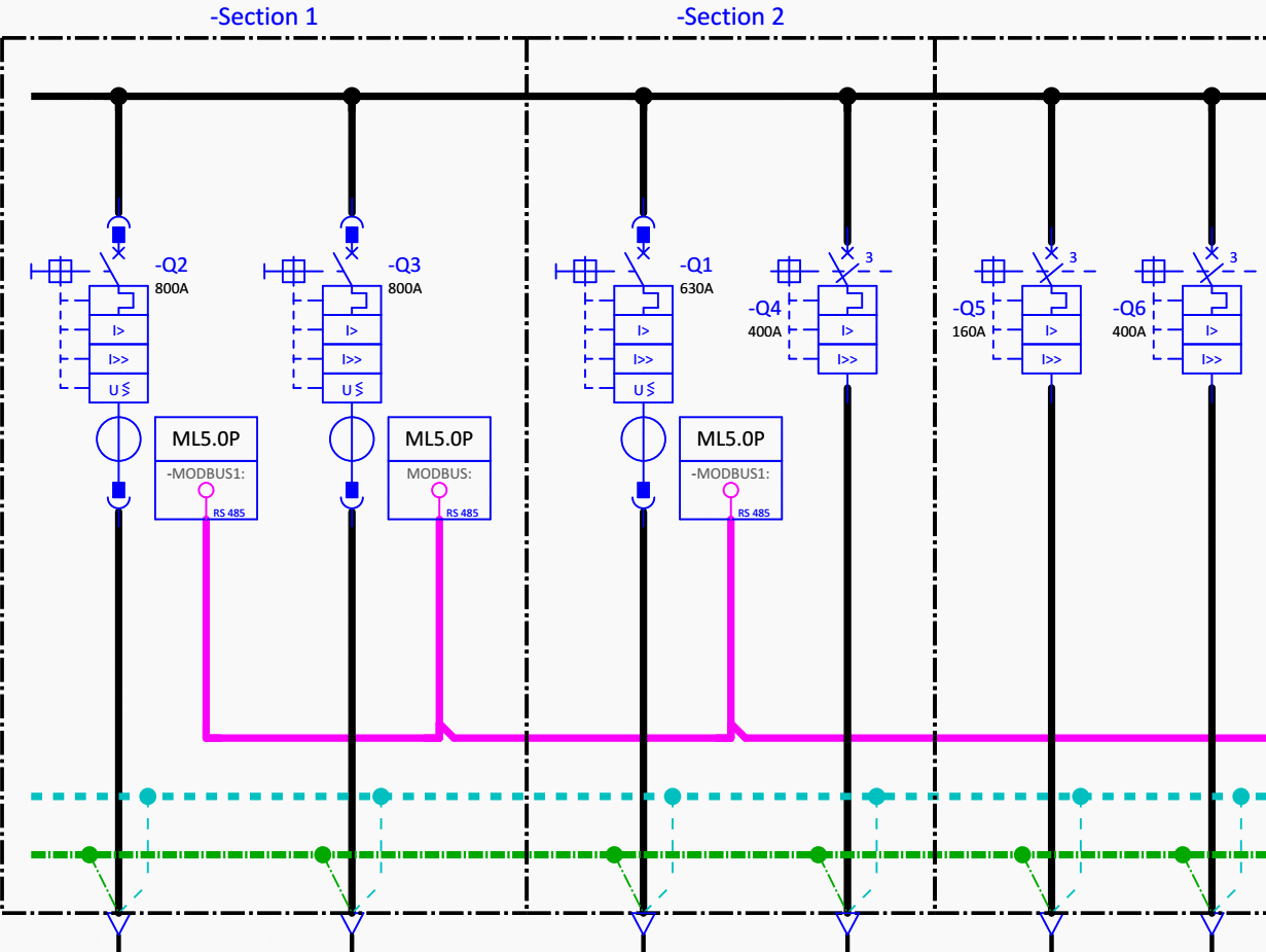
In Figure 1 main low voltage distribution board consisted of five sections, i.e. cubicles, is shown in the form of single line diagram (SLD).
Nowadays, usually =FUNCTION +LOCATION -PRODUCT principle for creation of project tag for equipment is used, according to IEC 81346. Dashed rectangles are most often designation for so called location box, which may be a switchboard, control panel, substation or similar in example.
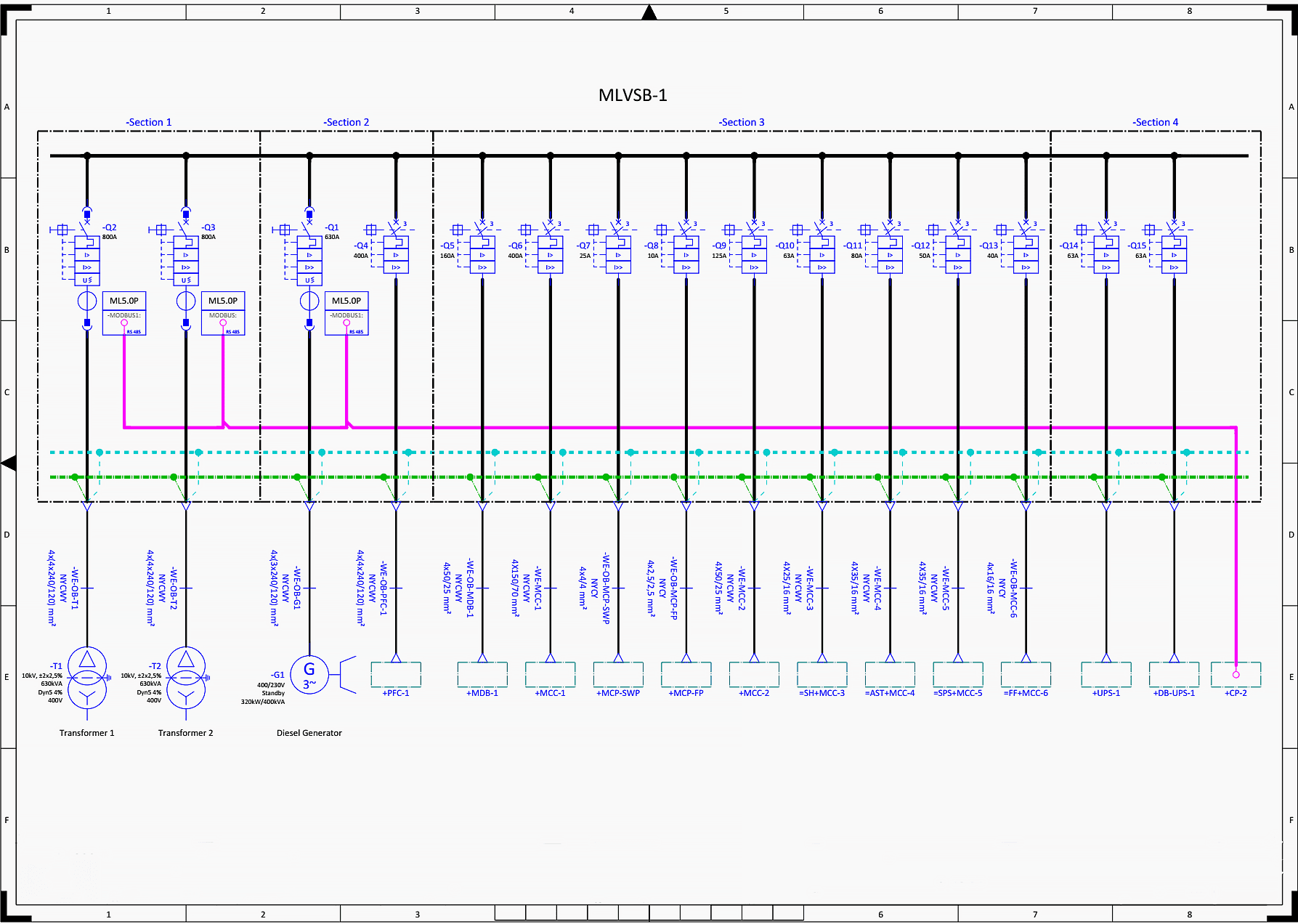
There are three incomings: transformer 1 (-T1), transformer 2 (-T2) and generator (-G1) and twelve outgoings, so fifteen circuit breakers in total are shown. “Standby” generator means that it will be started and used for supply only in case when grid supply isn’t available, i.e. in case when neither of two transformers is capable to provide power supply.
Note that standby rating of generator (in this case 320kW/400kVA) differs from some other, e.g. prime rating of same generator.
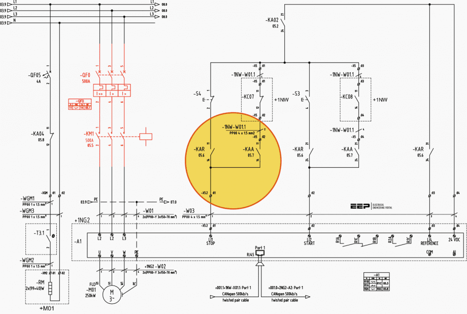
Black continuous line represents three live conductors or busbars (L1, L2, L3), blue dashed line stands for neutral (N), while green dash-dot line is protective earth (PE). This can be easily concluded, but it is better to be clearly marked in drawing.
I advise you to download and open above scheme in PDF format to follow discussion more efficient.
Following main electrical characteristics of the switchboard are usually shown above main busbars:
- Rated supply voltage (e.g. 3×400/230V, 50Hz)
- Rated current (e.g. 1000A)
- Short duration withstand current (e.g. 16kA/1s)
This example doesn’t contain those data, which may be considered as a drawback.
Rated power of transformer is 630kVA. Since there is N conductor in each supply cable, while transformer’s secondary is shown to be delta connected, we may suspect that later is a drawing error. Probably secondary is grounded wye and primary is delta connected, which is typical choice for this type of application.
If we look closer to transformer’s characteristics, we will find the answer, since the winding connection is specified to be Dyn5. That means primary winding (capital letter) delta connected (D) and secondary winding (small letter) wye connected (y) with neutral (n) terminal. 5 “hours” or 5×30=150 degrees is the phase shift between corresponding primary and secondary voltages, while 4% is short circuit voltage and relative impedance.
Related electrical guides & articles


Miodrag Kokotovic
Graduated from Faculty of Electrical Engineering, within University of Belgrade, in the field of electrical power systems. Expert in electrical part of tender preparation, design, procurement, construction and commissioning of treatment plants and pumping stations, electrical power quality and energy management.Profile: Miodrag Kokotovic
