Electrical working drawings
Every electrician, in every branch of electrical work, will need to consult and understand the information presented on electrical drawings to locate the various outlets, the routing of circuits, the location and size of panelboards, and other similar electrical details.

A complete set of working drawings for the average electrical system in industrial, commercial, and large residential projects will usually consist of the following:
- Plot plan showing the location of the building on the property and all outside electrical wiring, including the service entrance. This plan is drawn to scale with the exception of the various electrical symbols, which must be enlarged to be readable.
- Floor plans showing the walls and partitions for each floor level. The physical locations of all wiring and outlets are shown for lighting, power, signal and communication, special electrical systems, and related electrical equipment.Again, the building partitions are drawn to scale, as are such electrical items as fluorescent lighting fixtures, panelboards, and switchgear. The locations of other electrical outlets and similar components are only approximated on the drawings because they have to be exaggerated to be readable.
- Power-riser diagrams to show the service-entrance and panelboard components.
- Control wiring schematic and single-line diagrams.
- Schedules, notes, and large-scale details on construction drawings.
To be able to “read” electrical as well as other types of drawings, one must become familiar with the meaning of symbols, lines, and abbreviations used on the drawings and learn how to interpret the message conveyed by the drawings.
Let’s start with 10 simple questions. Answers are at the bottom, and please don’t peek :)

Question #1
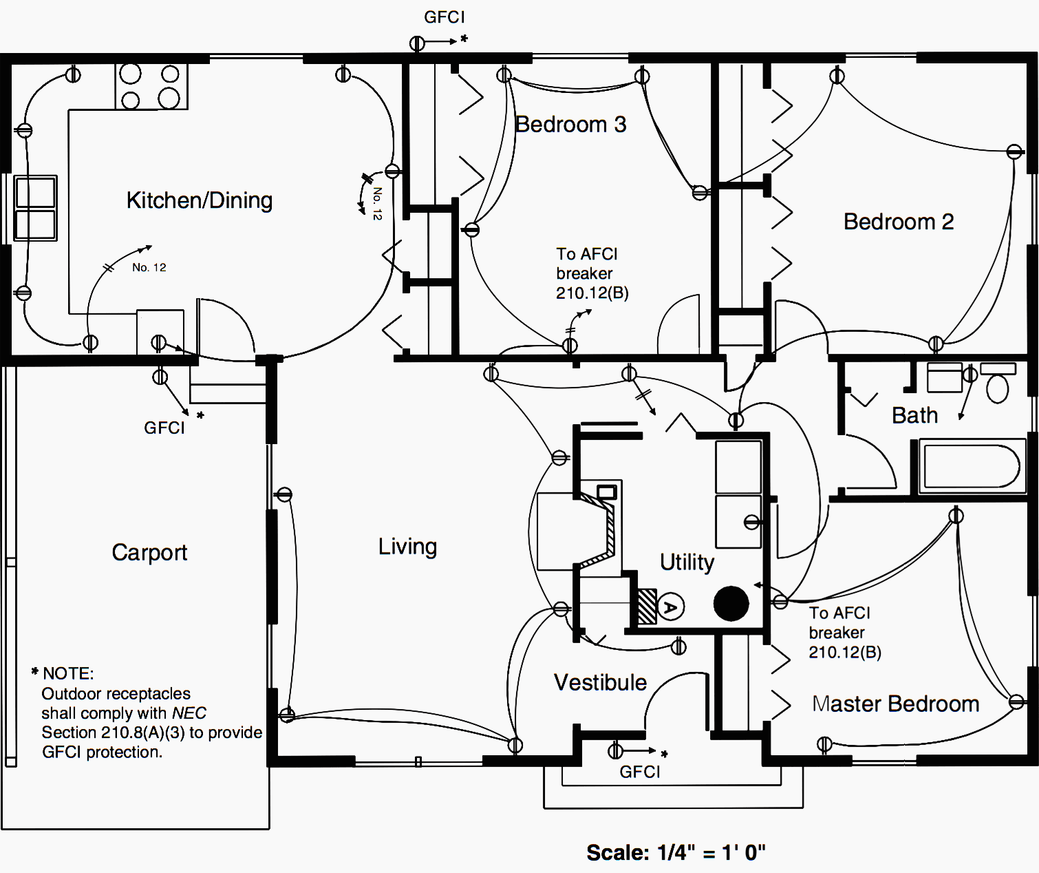
How many branch circuits are shown in Figure 1?
- Five
- Six
- Seven
- Eight
Question #2
How many duplex receptacles are installed outside the building in the drawing in Figure 1?
- One
- Two
- Three
- Four
Question #3
To comply with the NEC, what device must be used on all three outside duplex receptacles shown on the drawing in Figure 1?
- Double-pole circuit breaker
- A ground-fault protector (ground-fault circuit interrupter)
- A single-pole mercury switch
- A 40-amp circuit breaker

Question #4
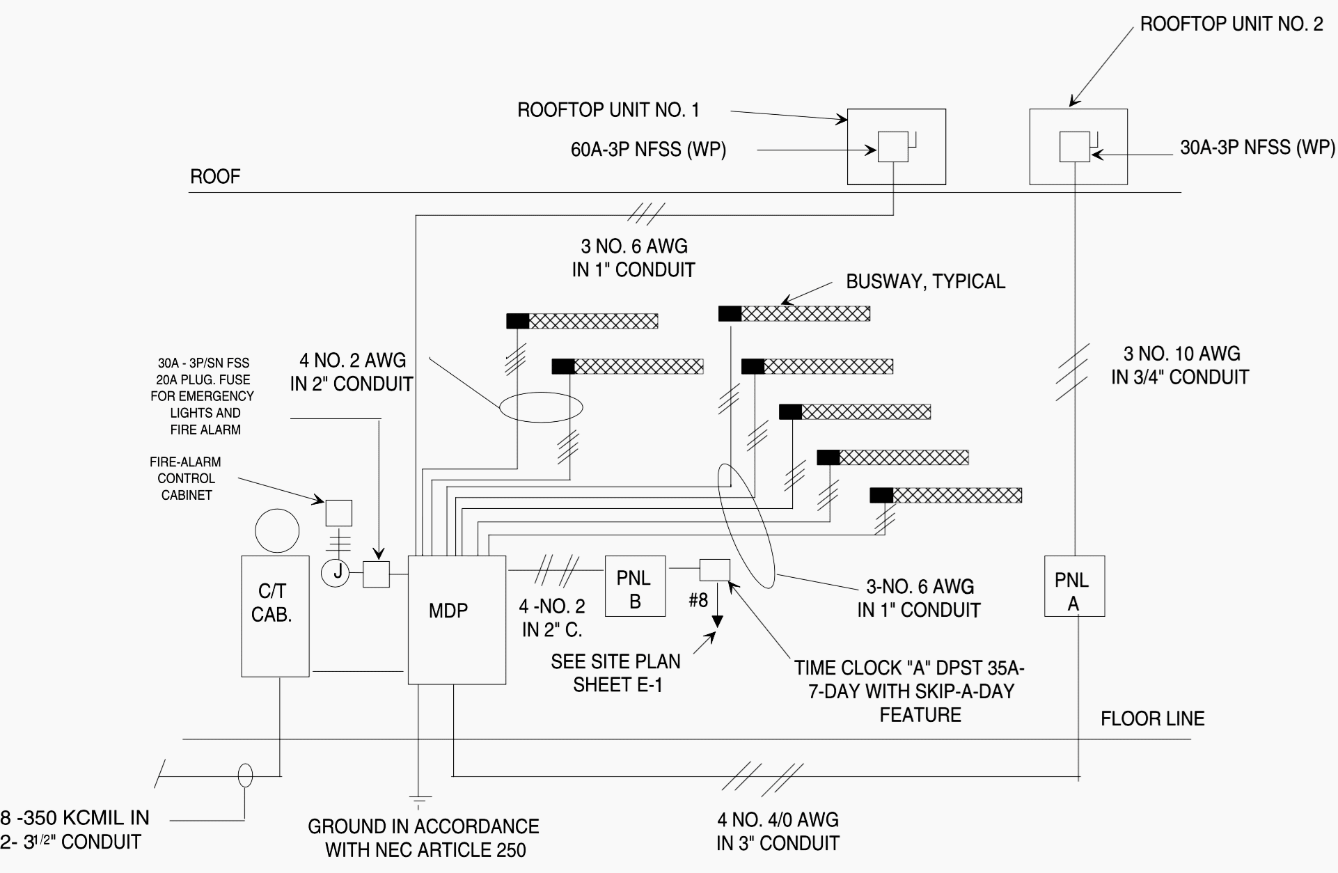
In the power-riser diagram in Figure 2, what does “C/T cab.” stand for?
- Central telephone cabinet
- Current transformer cabinet
- Control terminal cabinet
- Central termination cabinet
Question #5
Which of the following best describes where the type and size of overcurrent protection may be found?
- Floor plans
- Lighting-fixture schedule
- Panelboard schedule
- Cross-sectional views
Question #6
What wire size and how many conductors are specified for the feeder circuit supplying the rooftop unit No. 2 in the drawing in Figure 2?
- Three No. 1 AWG
- Three No. 10 AWG
- Four No. 2 AWG
- Two No. 4 AWG
Question #7
How many sections of busway are specified in the drawing in Figure 2?
- 7
- 10
- 17
- 27

Question #8
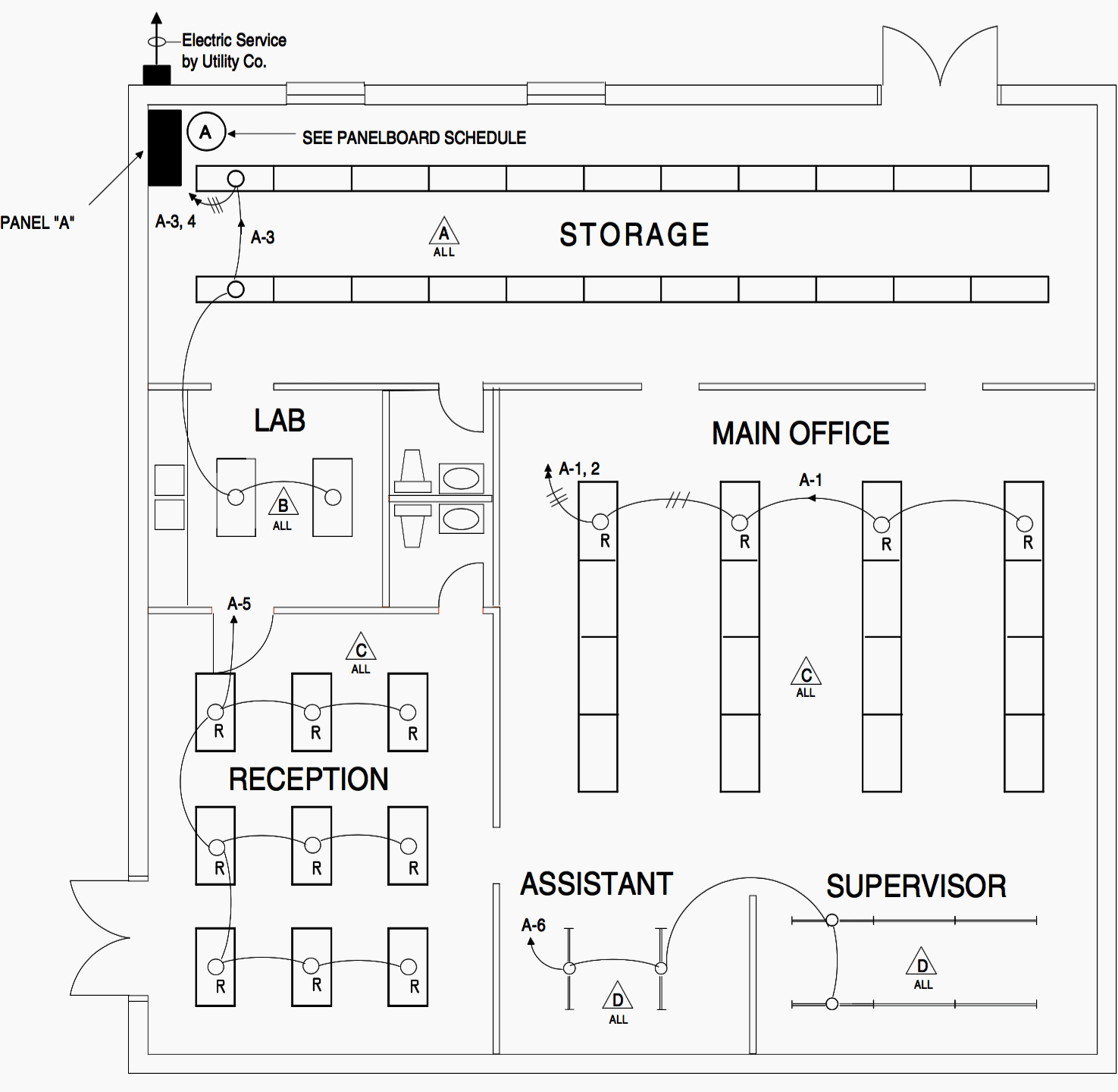
If each of the Type C lighting fixtures in Figure 3 have a total lamp and ballast load of 200 volt-amperes, what is the total connected load of circuit A-1 (in volt-amperes)?
- 1600 volt-amperes
- 1700 volt-amperes
- 1800 volt-amperes
- 1900 volt-amperes
Question #9
What is one good reason that circuit lines are drawn curved rather than straight?
- This is how conduit is installed in buildings
- To enable the drafters to route the lines around partitions
- So as not to confuse the circuit lines with building lines
- Curved lines are easier to draw on CAD systems than straight lines
Question #10
What do arrowheads placed on circuit lines mean?
- Designates the room in which the circuit is installed
- Home runs to the designated panel
- The direction of current flow
- Designates that the circuit is to be controlled by a wall switch
Answers
NEC articles mentioned in answers you can observe in a free draft version of NEC 2014 //
Question #1
Answer: C
Two circuits serve the kitchen, 1 serves the master bedroom, 1 serves both bedroom #2 and bedroom #3, 1 serves the living room/vestibule, and 1 supplies the GFCI circuit which supplies protection to the carport receptacle, both front and rear receptacles, NEC Section 210.8(A). One circuit supplies the GFCI receptacle in the bathroom, NEC Section 210.11(C)(3).
Question #2
Answer: C
Three outside duplex receptacles are shown by symbol on the floor-plan drawing and also described in the Note.
Question #3
Answer: B
A ground-fault protector is indicated by notes on the drawing in Figure 1. See Section 210.8(A)(3) of the NEC.
Question #4
Answer: B
The service conduit and conductors enter the C/T cabinet where current transformers (CTs) are used in conjunction with the electric meter for metering the amount of power used.
Question #5
Answer: C
The panelboard schedule on drawings usually indicates the type and size of overcurrent protection.
Question #6
Answer: B
The note adjacent to the feeder indicates three No. 10 AWG conductors.
Question #7
Answer: A
There are seven sections shown in the power-riser diagram in Figure 2.
Question #8
Answer: A
Since there are eight fixtures fed by this circuit, 8 × 200 = 1600 volt-amperes.
Question #9
Answer: C
When circuit lines are drawn straight, they are sometimes confused with the building lines. Thus, Answer C is one good reason for drawing curved circuit lines.
Question #10
Answer: B
Arrowheads are used to indicate a home-run to a panelboard.
Reference // Electrician’s exam preparation guide (Buy hardcopy from Amazon)



I didn’t answer so much, i got my certified but zero experience. Companies don’t hire people with some record. I finish in 2018 with no driver license until October 2021 and now i need transportation. Always Buts and good article by the way.
Thanks for the very informative post .
Hi , I would like to receive information about the electrical worksite
I like EEP documents ,l would like you to please cover how to link boiler draft to ID motor VFD to achieve automatic control.
Doesn’t apply to New Zealand, UK or Australian situations where power supply is 230/400V and governed by a different set of rules & legislation.
Gained my qualifications in CANADA before moving back home to the COOK ISLANDS. Hold both RSE Canada and Registered NZ license.
Currently employed as Electrical Tutor at COOK ISLANDS TERTIARY TRAINING INSTITUTE. Your Theory posts are very good
That was really informative. BTW, thanks for the hidden clues. I found most of them.
you are best of all. thanks your lectures note and books
Great post.. What’s your preference for electrical drawing tool that is compatible with the industry and friendly user..
very knowledgeable posts
Thank you this is a good one
As a Dutch electrical engineer i’m trying my best to understand but it is totally different from the european standard. Cool to spot the differences. Thanks for the great content. If you want some european stuff for you site please contact me. I have some drawings from my house and pictures of european electrical installations.
Yeah I have some pictures too that you can use. I love your site and hope that it sticks around for a long time. You can contact me here: http://www.ttnengineering.com/
Bart,
Could you share with me the European electrical rules, symbols, etc? It’s difficult for me to understand the European electricals drawings.
Hi Bart,
I am here to thank you for this article and the rest posted so far. I followed your articles closely and they enhanced my theoritical and practical knowledge on the subject. I sincerely applaud your generousity and hope to read and learn more with you on this space.
I am an Electrician from Papua New Guinea