
Estimated Study Time: 31 minutes
Reading and interpreting drawings
Engineering tasks require a good skill in reading and interpreting information on drawings. Engineering drawings are the industry cornerstone of conveying detailed and precise information on how to construct, troubleshoot, maintain, and operate a system. Basic requirements are needed to understand the way of reading these drawings: rules, basic symbols, and industry conventions.
 Practical advice in successful reading single-line, schematic, P&ID, logic, and wiring diagrams
That being said, a pre-requisite of learning how to read the drawings is to know how to read non-drawing areas of a print. Vendors have variant drawing formats and information, so all drawings will have different information from these addressed here, but these drawings are usually similar.
This article provides tips for different drawing types that help to grasp these drawings’ main principles quickly. These drawings cover single-line, schematic, wiring, logic, and P&ID drawings that are found in the industry. Prior to delving into more details of these drawings, non-drawing topics are usually overlooked in explaining the drawing reading basics.
Then, the mentioned drawing types are introduced and some tips are presented to help to interpret these drawings. This article does not explain these drawings, instead one must have some sort of basic understanding of the drawings.
1. Drawing Anatomy
Engineering drawings are classified into the following areas:
- Title block
- Grid system
- Revision block
- Notes and legends
- Engineering drawing (graphic portion)
The first four items represent the non-drawing parts that are essential in reading the drawing itself. Hence, a brief description of each item is presented in this article.
1.1. Title Block
A title block is normally located at the bottom of a print, lower right-hand corner in particular. It has the all necessary information to identify drawings and verify their validities. Several areas comprise a title block as shown in Figure 1.
1.1.1. Title block first area
This area contains the drawing title, number, location, site, or vendor. The drawing title and the drawing number are used to identify and fill the required drawing. The drawing number is usually unique and consists of a code containing information about the drawing like site, drawing type, and system.
1.1.2. Title block second area
The second area encompasses the signatures and the dates of approval that provide information about when and who verified the drafted drawing for final approval. This information is invaluable in finding further data on the system design. Also, these referees can be helpful in discrepancy resolution and dispute settlements.
Figure 1 – Title block
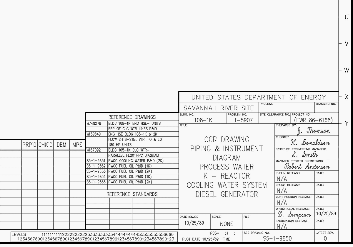
1.1.3. Title block third area
This block is the reference block that lists other drawings that are either related or cross-referenced on the underlying drawing. Obviously, the reference block is extremely important in locating additional information of a given system that can be found in other related drawings.
1.2. Drawing scale
Drawings are generally categorized to either with a scale or not to a scale. The former provides only functional information about the system while the latter render figures accurately. Furthermore, scale drawings allow systems that are too large to be drawn full size and vice versa. In other words, small systems could be enlarged such that their details are noticeable.
Scale drawings often provide the means to fabricate or assemble a system.
The drawing scale is ratio-based as illustrated in Table 1.
Table 1 – Drawing scale
| Drawing scale | |
| 1″=1″ | 1 inch on drawing equals 1 inch on actual. |
| Stated as FULL SIZE in the drawing scale box | |
| Measured dimension on drawing is the same as the actual dimension | |
| 3/8″=1’ | 3/8 inches on drawing equals 1 foot on actual |
| Called “3/8 scale” | |
| 1/2″=1’ | 1/2 inches on drawing equals 1 foot on actual |
| Called “1/2 scale” | |
1.2.1. Grid System
Drawings complexity varies according to the system application. Complex drawings make it challenging to locate a specific point or equipment on a drawing. This becomes more difficult when moving between drawings to trace cables or pipe runs that continue to other drawings. This is why drawings utilize a grid system, especially for Piping and Instrument Drawings (PID) and electrical schematic diagrams.
The grid system might consist of letters, numbers, or both that run horizontally as well as vertically around the drawing as depicted in Figure 2.
Figure 2 – A grid system example
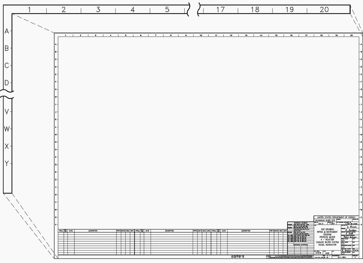
Drawings are divided into smaller blocks, each has its own unique grid identifier that is composed of two letters or numbers. For instance, a cable that continues from a drawing to another, the second drawing references the other drawing and it uses the grid coordinates to locate the continued cable, thereby facilitating the search process significantly.
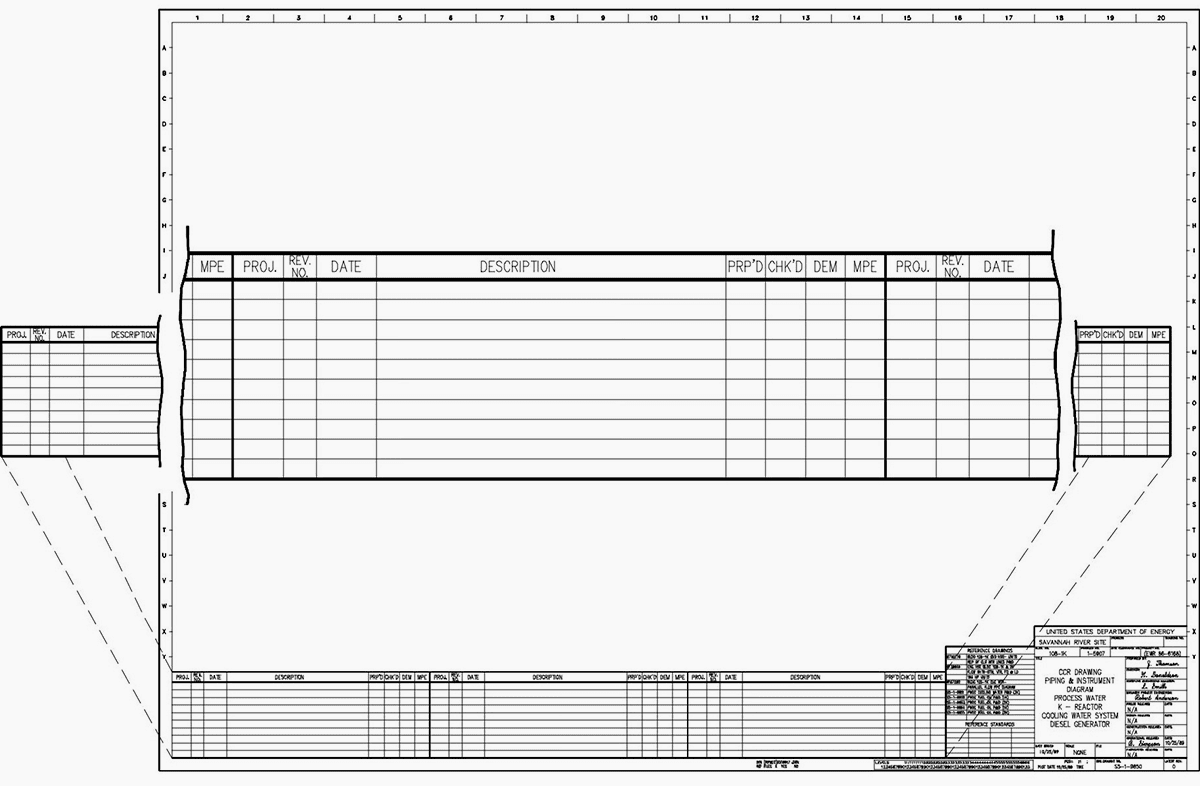
1.2.2. Revision Block
Changes made to systems must be redrafted and reissued. A drawing first issue is called revision zero, and the revision block is empty. The revision block is filled with a revision number, a revision date, a title, or a revision summary at every drawing revision release. The revision number could be part of the drawing number that appears at the end of this drawing number or in its own separate block (see Figure 3).
Whenever a system modification is held, the drawing is updated to reflect such modifications, the revision number is incremented by one, the revision number in the revision block is updated to represent the new revision number. Note that the drawing number remains the same. The old revision drawing is filed for historical purposes.
Figure 3 – Revision block
1.2.3. Tracking Changes
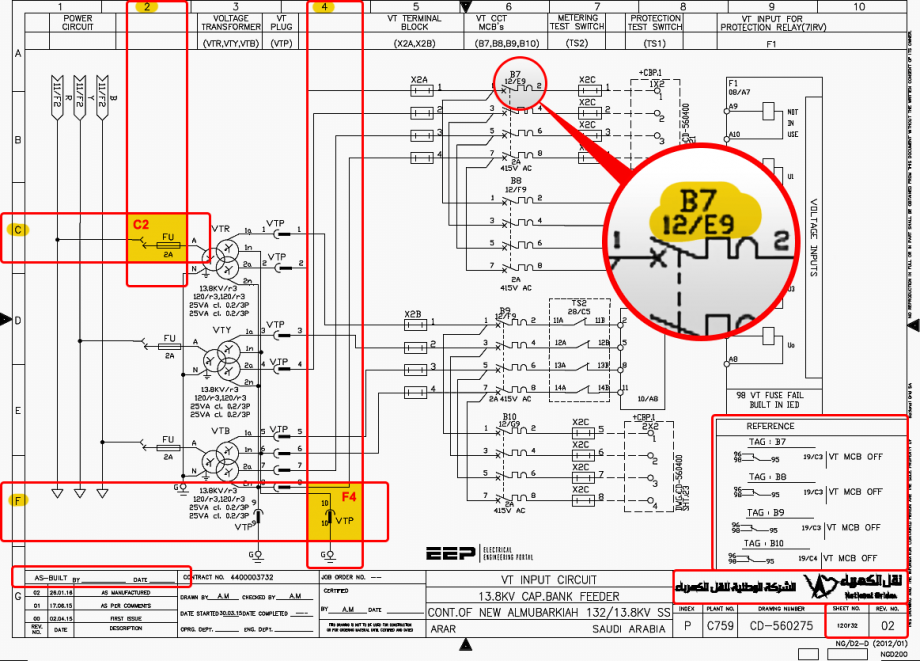
Two approaches are commonly used to indicate changes made on drawings in their corresponding revisions. The cloud method encloses each change within a cloud-shaped box as illustrated in Figure 4. The other approach is to place changes within circles, triangles, or any other shapes with the revision number written next to each modified portion of the drawing as indicated in Figure 4.
The cloud approach indicates the changes from the most recent revision whilst the other approach represents all revisions to the drawing since all previous revision circles/triangles remain on the drawing. Both the revision number and the revision block are useful in tracing the evolution of a system by comparing the various revisions.
Figure 4 – Methods to indicate changes
1.2.4. Notes and Legends
Symbols and lines to drawings are what genes to chromosomes, which both form the basic building block for larger systems. To a great extent, symbols are self-explanatory, but a few symbols shall be elaborated for each drawing.
The notes and legends section list and illustrate special symbols as shown in Figure 5. Moreover, a designer can add any information that is necessary to interpret correctly the drawing. It is essential to view this section prior to proceeding to the drawing contents so as to fully understand the symbols and conventions used in the drawing package.
Related electrical guides & articles


Salem Alshahrani
Electrical engineer (BEE & Meng). Specialized in substation design, especially in LV/MV switchgears and transformers. Passionate in power system planning, analysis, and stability studies.Profile: Salem Alshahrani
