
Estimated Study Time: 9 minutes
Real service conditions
The various service conditions for the MV equipment inside substation are linked to the design of the installation, the design of the operating room, the site and the application surrounding the installation, and finally, the seasons.
 How to specify real service conditions for LV/MV equipment inside a substation
The combination of these parameters generates a matrix that can impact the lifespan of the products. Beyond atmospheric corrosion certain environments can become more severe for electrical MV components, and even in LV, if they have a definition of pollution level different in comparison with MV.
The table below makes it possible to understand how applicable standards or technical specifications could interact, through easily identifiable installation criteria.
As indicated in the IEC 62271-1 standard, condensation may occasionally occur even under normal conditions. The standard goes on to indicate special measures concerning the substation facilities that can be implemented to prevent condensation.
Environmental factors
However, when selecting environmental factors for a certain product application on-site it is recommended to check these conditions and influences for single, combined and sequential environmental factors as they occur.
This analysis must be cross-checked with the ambient conditions for which the product has been designed, according to its respective standard.
Use under severe conditions
Under certain severe conditions concerning humidity and pollution, largely beyond the normal conditions of use mentioned above, correctly designed electrical equipment can be subject to damage by rapid corrosion of metal parts and surface degradation of insulating parts.
Remedial measures for condensation problems
- Carefully design or adapt substation ventilation.
- Avoid temperature variations.
- Eliminate sources of humidity in the substation environment.
- Install a Heating, Ventilation, Air Conditioning unit (HVAC)
- Make sure cabling is in accordance with applicable rules.
Remedial measures for pollution problems
- Equip substation ventilation openings with chevron-type baffles to reduce entry of dust and pollution especially when the transformer is installed in the same room with switchgear or controlgear.
- Install the transformer in a different room, or use more efficient ventilation grids if any,
- Keep substation ventilation to the minimum required for evacuation of transformer heat to reduce entry of pollution and dust.
- Use MV cubicles with a sufficiently high degree of protection (IP).
- Use air conditioning systems or air forced cooling with filters installed in air inlet to
restrict entry of pollution and dust. - Regularly clean all traces of pollution from metal and insulating parts
Ventilation in substation
Substation ventilation is generally required to dissipate the heat produced by transformers and other equipment, and to allow drying after particularly wet or humid periods. However, a number of studies have shown that excessive ventilation can drastically increase condensation.
HV/LV Prefabricated substation
Any installation of any transformer in the same room with MV and LV switchgear compartment will impact the lifespan of the products, for the following reasons:
- Any air change generated by the transformer heating reduces the impact of irradiance. This air ow change is natural convection.
- Any separation of the transformer by a partition wall with the HV and LV switchgear compartment will improve the service condition of the switchgear for moderate climates.
- Any switchgear installation without a transformer in the room, resulting in no air change, should be installed in a thermal insulated enclosure protecting it from outdoor service conditions (Dust, humidity, solar radiation…) especially for very hot and cold climates.
Ventilation should therefore be kept to the minimum level required. Furthermore, ventilation should never generate sudden temperature variations that can cause the dew point to be reached.
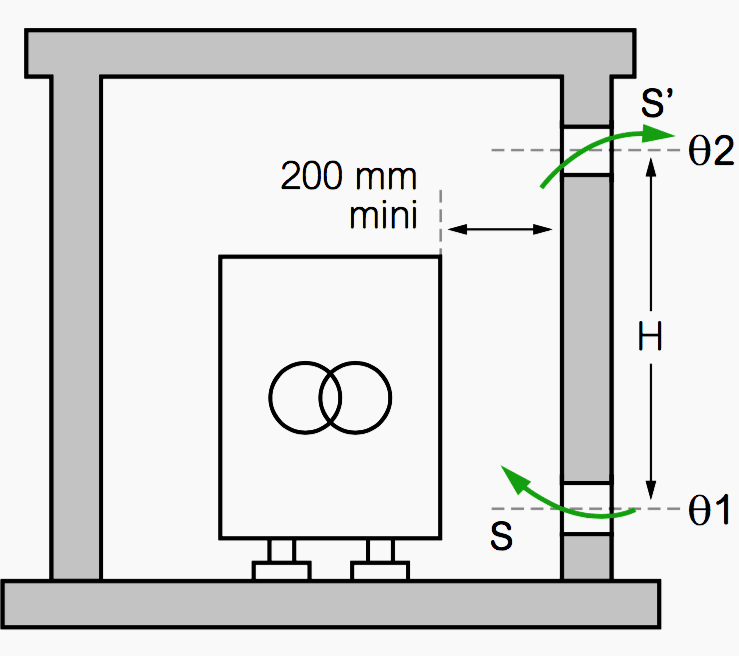
Natural ventilation, Figure 1, being the most used for MV installations, a guideline for sizing the air entry and exit openings of HV/LV substations is presented hereafter.
Calculation methods
The scope is for buildings and prefabricated enclosures using same ventilation grids for air inlet and air outlet. A number of calculation methods are available to estimate the required size of substation ventilation openings, either for the design of new substations or the adaptation of existing substations for which condensation problems have occurred.
The basic method is based on transformer dissipation by natural convection. See Figure 2 below.
Figure 2 – Coefficient of pressure losses defined by air flow tests
![]()
IP23 Chevrons blade
(ξ = 33 if α = 60°, and ξ = 12 if α = 90°)
Space between blade is extended to the maximum allowed by the degree of protection IP2x so below 12.5mm.
Other openings:
IP43 Additional vermin proof wire mesh with 1mm2 openings using a wire thickness 0.6mm, complete covering ventilation grid ≥ ξ + 5
IP23 38mm × 10mm openings only: ξ = 9
The required ventilation opening surface areas S and S’ can be estimated using the following formulas, with or without knowing the air ow resistance coefficient of the ventilation grids.
- Formula 1: Qnac = P – Qcw – Qaf is the dissipation by natural air circulation [kW]
- Formula 2:
S = 1.8 × 10⁻¹ Qnac/√H if air flow resistance is unknown
S’ = 1.1 × S – S and S’ are efficient net area.
Chevrons blade- S = Qnac / ( Kx √ H × (θ2 – θ1)3 ) with K = 0.222 (1 / ξ) see Fig C
- S’= 1.1 × S – S and S’ are the gross area.
Where:
- Qnac is the dissipation by natural air circulation [kW] P is the sum of the power dissipated [KW] by:
- The transformer (dissipation at no load and due to load)
- The LV switchgear
- The MV switchgear
- Qcw is the heat dissipation by conduction through the walls and ceiling [kW] (Assumption Qcw = 0 in the example).Losses by conduction through the walls, the ceiling (Qcw) and the slab can be expected from 200W for a thermal insulated housing, up to 4KW for a 10m2 prefabricated substations using concrete material.
- Qaf is the heat dissipation by forced air circulation [kW] (Assumption Qaf =0 in example) θ1 and θ2 are, respectively, the air temperatures of inlet and outlet [°C]
- ξ is the resistance coefficient of the pressure losses linked to the design of the ventilation grid.
- S is the lower (air entry) ventilation opening area [m2] as mentioned formulas 1 and 2 S’ is the upper (air exit) ventilation opening area [m2] as mentioned formulas 1 and 1
- H is the difference in height between mid-outlet surface and mid-height of transformer [m]
- (θ2 – θ1) is the air temperature rise which reflects the double of the transformer overheating for an oil immersed transformer (Loading guide IEC 60076-7) and the single transformer overheating for dry-type transformer (Loading guide IEC 60076-11).
Reference // MV Technical Guide by Schneider Electric
Related electrical guides & articles


Edvard Csanyi
Hi, I'm an electrical engineer, programmer and founder of EEP - Electrical Engineering Portal. I worked twelve years at Schneider Electric in the position of technical support for low- and medium-voltage projects and the design of busbar trunking systems.I'm highly specialized in the design of LV/MV switchgear and low-voltage, high-power busbar trunking (<6300A) in substations, commercial buildings and industry facilities. I'm also a professional in AutoCAD programming.
Profile: Edvard Csanyi
