
Estimated Study Time: 9 minutes
General protection recommendations
The protection that is recommended and commonly applied for transformers is summarized in the following figures. It should be noted and recognized that these are general recommendations, not strict.
 Recommended and commonly applied protection for transformers
More or less protection may be applied for any specific situation and will depend on local circumstances and individual preferences.
Contents
- Individual transformer units
- Parallel transformer units
- Redundancy requirements for bulk power transformers
1. Individual transformer units
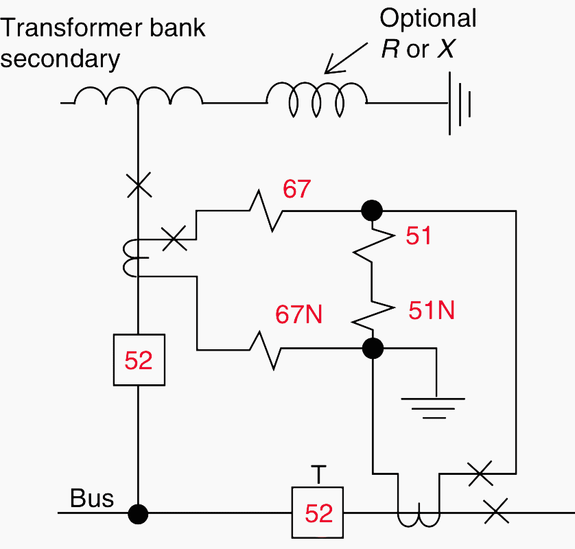
Figure 1 summarizes the protection for banks where fuses are used on the primary. For larger or important banks in this category, an overall differential protection may be applied by using CTs in the transformer primary bushings, or a ground differential.
Both require primary source tripping.
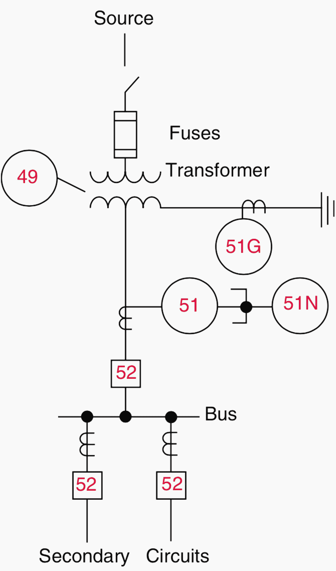
Common connection shown with delta on the source (primary) side and wye-grounded on secondary side. Other possible connections: delta–delta, wye–wye, or primary-wye– secondary-delta.
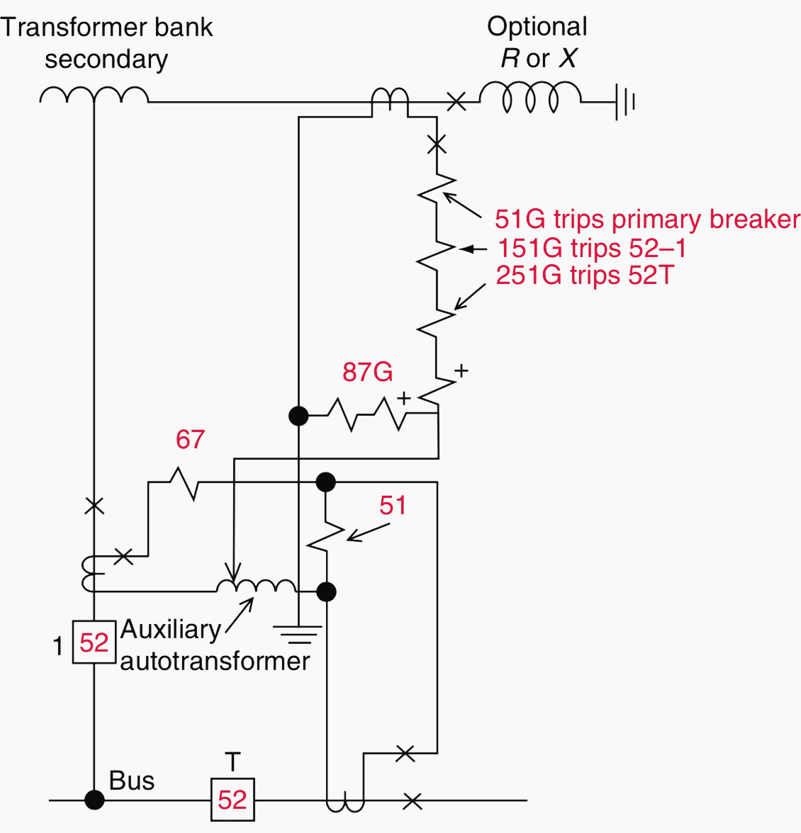
For transformer banks with primary breakers, the protection is summarized in Figure 2.
Relay 51G provides backup protection for secondary bus and feeder faults and must be time-coordinated, with other ground relays protecting the various feeder circuits on the secondary bus. Similarly, phase relays 51 must be coordinated with the phase relays on the feeders.
Relay 51G is set with a longer time and to coordinate with 51G.
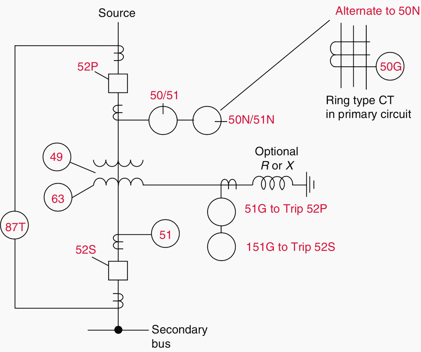
Common connection shown with delta on the source (primary) side and wye-grounded on the secondary side. Other possible connections: delta–delta, wye–wye, primary-wye– secondary-delta, three-winding, or autotransformer.
52S may be omitted in some applications requiring 151G to coordinate with and trip the secondary circuit devices, if used.
2. Parallel transformer units
The protection for transformer banks where the secondaries are connected together by a bus tie breaker is summarized in Figure 3(a,b,c).
The arrangement shown is typical for large- or critical-load substations, especially for industrial plants. The loads are supplied from separate buses that are connected together by a bus tiebreaker (52T) that may be operated either normally closed (NC) or normally open (NO).
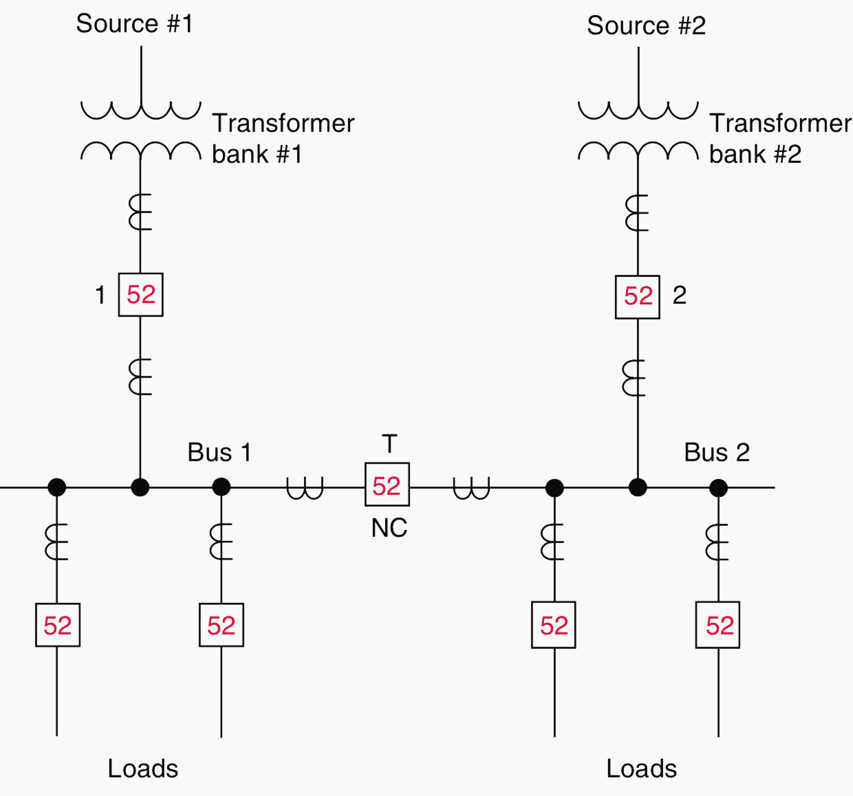
If operated NO, the protection of Figure 1 or Figure 2 is applicable. If operated with 52T NC, the protection of Figure 1 and Figure 2 is applicable with the secondary side modified (see Figure 3b or c).
With the bus tiebreaker closed, there is a possibility for the interchange of power between the two sources. Here, current flows from one source through its transformer, the secondary buses, and back through the other transformer to the second source. Generally, this is neither desirable nor permitted.
To prevent this operation, directional time–overcurrent relays (67, 67N) are applied to each transformer.
The single-line connections are shown in Figure 3b and Figure 3c, with complete three-line connections in Figure 4 .
Load current certainly flows through the relay, but normally not in the operating direction. The low tap continuous rating must not be exceeded by increasing the maximum load current.
The 67 time setting must coordinate with the protection on the transformer primary. When used, the ground relay can be set on minimum setting and time, because coordination is not necessary.
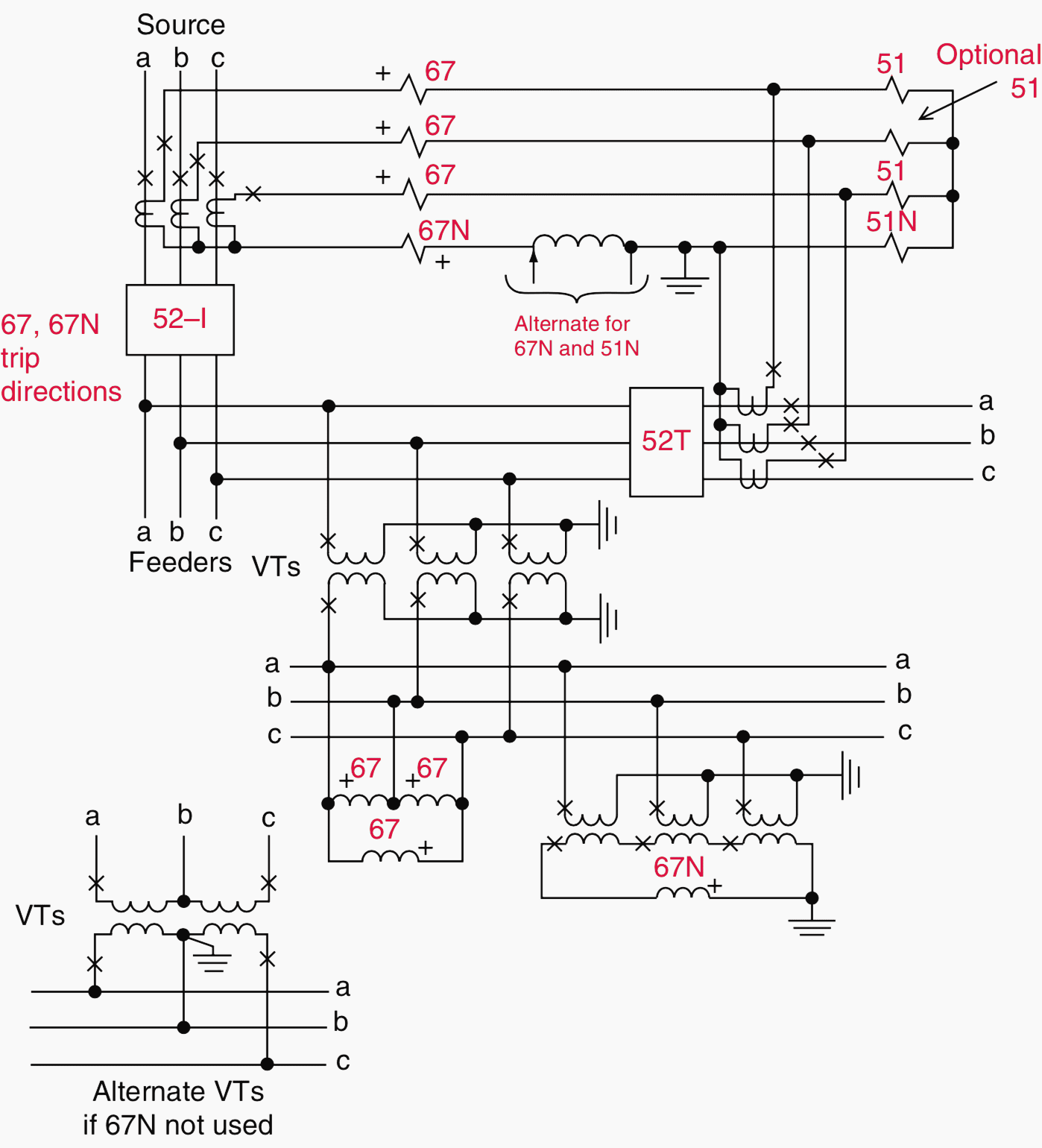
The inverse-time–overcurrent relays (51, 51N) provide bus protection and backup protection for the feeder circuits. These relays trip both 52–1 (or 52–2) and 52T. This is a partial differential connection and these units must be time-coordinated with the protection on the several feeders that are connected to the bus.
Only two-phase relays are required, but the third relay (shown optional in Figure 4) provides additional redundancy. When a ground differential is used, as illustrated in Figure 3c, 67N and 51N are omitted.
Ground-fault backup is provided by 51G, 151G, and 251G inverse-time overcurrent relays (Figure 3abc). Relay 251G provides bus ground-fault protection and backup for the feeder circuit ground relays. It must be time- coordinated with these. It trips the bus tie 52T, as the fault could be either on the bus or on the associated feeders.
If the fault continues to exist with the bus tie open, relay 151G trips breaker 52–1 (or 52–2). Thus, 151G must coordinate with 251G. If the fault persists, it is between the secondary breaker, in the transformer winding, or in the grounding impedance.
Relay 51G set to coordinate with 151G is the last resort. It trips the high-side or primary breaker to remove the transformer from service.
3. Redundancy requirements for bulk power transformers
When transformers are connected to bulk power systems, redundancy requirements for related protection need to be addressed. To provide the required redundancy, two separate differential schemes may be applied.
Redundancy for transformer faults may also be obtained by a differential scheme and sudden pressure.
In such application, the sudden pressure protection needs to be supplied with additional protection for faults on the transformer bushings and leads, as sudden pressure devices will not respond to faults in these areas. Redundant schemes for disconnecting the transformer from the system when a high-side breaker is not applied can be obtained by using various combinations of the methods.
For example, although expensive, two separate transfer trip systems may be applied. A cheaper alternative is to combine a transfer trip scheme and a fault switch. It may be possible to delay closing the fault switch for a few cycles to allow time for the transfer trip scheme, provided it is operational, to deenergize the failed transformer before the closing of the fault switch.
This would spare the power system from being subject to a solid fault when the fault switch closes, whenever the transfer trip scheme works properly.
When a high-side breaker is applied and it fails to operate, breaker failure protection is required to enable isolation of a faulted transformer. The breaker failure scheme may require application of a fault switch, transfer trip scheme, or a second interrupting device if other local breakers are not available to isolate the transformer.
Reference // Protective Relaying Principles and Applications by J. Lewis Blackburn and Thomas J. Domin (Purchase hardcopy from Amazon)
Related electrical guides & articles


Edvard Csanyi
Hi, I'm an electrical engineer, programmer and founder of EEP - Electrical Engineering Portal. I worked twelve years at Schneider Electric in the position of technical support for low- and medium-voltage projects and the design of busbar trunking systems.I'm highly specialized in the design of LV/MV switchgear and low-voltage, high-power busbar trunking (<6300A) in substations, commercial buildings and industry facilities. I'm also a professional in AutoCAD programming.
Profile: Edvard Csanyi

Very informative document, that is great
Good morning
To keep a record of your articles I used to save them, first with the option to print and then saved as PDF file, but since maybe 3-4 weeks the system when I tried to print them only pops out one black page, so I could not keep the articles that you sent me.
Could you tell me the best way to keep and save your articles?
Thanks
Victor Llanos
Hi Victor, saving technical articles to PDF is a premium feature. You have to sign up for a premium plan to do so.
Very Good
Thanks, it was great I have a great interest in the field of the protection of power systems
Demande formations
Edvard,
For articles on system protection generally – not just this particular one – it would be useful to many readers, especially American or East Asian ones, to give a brief reminder of the properties of commonly used relays, such as the 51 and 52 series & others. A table could briefly summarize their main properties, or even a link to the manufacturer’s website.
Thanks for the article.
Regards, David.