
Estimated Study Time: 10 minutes
Energy waste savings
As savings in terms of costs are the main concern for the operators, the first approach is to try to reduce electrical energy losses in buildings. Also, the electricity supply network itself consumes energy. Moreover, if it is not suitably designed or adapted to user needs, the network is a cause of energy waste and at the same time will not provide satisfaction in terms of power quality and availability.
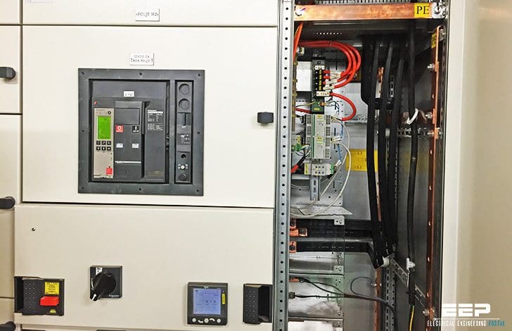 Three proven ways to reduce electrical energy losses in buildings (photo credit: Edvard Csanyi)
How to reduce electrical energy losses in buildings?
Let’s observe three proven ways to reduce electrical energy losses in buildings:
- Improve the power factor
- Reduce the harmonic ratio
- Reduce heat losses on the electricity supply network
1. Improve the power factor
Reactive power is consumed in the magnetic circuits of loads such as motors and by non- compensated fluorescent lighting. If not corrected, the current circulating in the conductors increases although the same level of active power is being used.
For cos φ = 1, the current and the voltage are in phase and the current is minimal.
The greater the deviation from this ideal value, the greater the degradation of operation with the following five consequences:
- Overcurrent on the electricity supply network on the site and on the public power supply network,
- Additional energy losses (Joule effect) across the network,
- Overloading and overheating of the transformers and a reduction in the available active power (see example calculation below),
- An end-of-line voltage drop which can induce abnormal operation of certain sensitive devices,
- In many cases, a financial penalty charged by the energy distributor (whose installations are also overloaded by the reactive power consumed by their customers), the calculation of which varies according to the country and the distributor.
Reactive power generators (capacitors)
The solution to this problem is to install reactive power generators (capacitors), either closest to the loads which consume it (local compensation) or at selected points on the electricity supply network (central compensation).
However, installations do not permanently function in the same configuration: circuits are switched, loads are activated or removed, motors start and stop. It is also undesirable to leave the compensation calculated for maximum loading permanently connected, as there is a risk of “over compensation” leading to overvoltages which can damage the installation and the equipment.
In practice, optimum compensation is possible using capacitors grouped in “steps”, with each step connected to the electrical circuit via a contactor controlled by a regulator subject to the measured power factor.
Example (adding power load to an existing industrial facility)

The requirement //
To add a power load P2 = 100 kW with cosφ = 0.7 to an existing industrial facility with a power transformer Sn = 630 kVA, to supply an overall active power load P = 450 W with cos φ = 0.8.
Preliminary checking //
- The apparent power consumed is S1 = P1 / cos φ = 450 / 0.8 = 563 kVA and
- The reactive power is Q1 = √(S12 – P12) = 338 kVAR
- The apparent power of the additional load is S2 = P2/cosφ = 100/0.7 = 143 kVA
- its reactive power is Q2 = √(S22 – P22) = 102 kVAR
The total apparent power to be provided by the transformer is S = √(P2 + Q2) where:
- P = P1 + P2 = 550 kW and
- Q = Q1 + Q2 = 440 kVAR i.e. S = 704 kVA
- The new power factor is cos φ = P / S = 0.78
The result //
The power of the existing transformer is insufficient to supply the overall load.
The solution //
Reactive power compensation Define the capacitor bank: to do this the corrected reactive power must allow the inequality:
- S = √(P2 + Q2) < 630 kVA therefore:
- Qmax = √(S2 – P2) = √(6302 – 5502) = 307 kVAR
- Q – Qmax = 440 – 307 = 133 kVAR to give a minimum cos φ = P / S = 550/630 = 0.873
- 200 kVAR capacitor bank is installed to give: Q = 440 – 200 = 240 kVAR and
- S = √(P2 + Q2) = √(5502 + 2402) = 600 kVA
where cos φ = P / S = 550 / 600 = 0.917. The cost is € 12,000 (automated capacitor bank).
Advantages:
- Savings:
- In active power corresponding to the heating of the circuits: 3,000 kWh / year, i.e. € 200 / year
- In the maximum power demand (in kVA): € 2,500 / year,
- In removing € 7,000 p.a. in penalties (halt to consumption of 250,000 kVARh p.a.).
- It is not necessary to replace the transformer with a more powerful model: a power reserve is still available.
- Operation of the transformer under better conditions leading to a longer service life.
- A short time required for return on investment: 1.3 years.
2. Reduce the harmonic ratio
“Harmonics” (currents or voltages with a frequency which is a multiple of the 50 or 60 Hz operating frequency) are generated by certain “non-linear” equipment, in particular those containing electronic components: domestic equipment, computers, inverters, variable speed drives, etc. They are superimposed on the current or voltage in the electricity supply network.
These harmonics travel upstream on the network and create a form of pollution for all other equipment, some of which is very sensitive. They are also the cause of energy losses due to the Joule effect which may reach 10%, in conductors, transformers and all other equipment.

Preserving the quality of electrical power (wave form, frequency, etc.) requires that these harmonics be reduced or eliminated: to do this, anti-harmonics filters are installed which are adapted to the network and the equipment in the building: their design requires highly specialized study.
In extremely specific industrial cases (furnaces used in metallurgy, welding machines) these filters are inadequate and the electricity supply network must be designed to take account of this function.
3. Reduce heat losses on the electricity supply network
These losses are produced by current flowing through all parts of the electricity supply network in the building (the Joule effect).
The replacement of old apparatus or equipment by more modern hardware can significantly reduce these losses:
1. Distribution transformers (up to 3 MVA)
Technological developments in materials and in particular laminations can reduce no-load losses from 15% to 20% irrespective of whether the transformer is of the oil-filled or dry type.
2. Electrical switchboards and enclosures
Research into distribution architectures has made it possible to reduce conductor lengths by approximately 40%, thus reducing energy losses due to the Joule effect by approximately 30% (see figure 1). Moreover, there is a possibility of savings through the choice of the electrical switchgear integrated into the switchboard.

This is the particular case of contactors, which often appear in some numbers in automated systems: for example, whereas the old “model D” contactor-circuit breaker unit on a 20 A motor- starter consumed a steady 20 W, a newer models only require 7 W and less.
UPS (Uninterrupted Power Supply)
Inverter efficiency varies according to the characteristics of the load supplied (in particular the power factor): modern technologies have allowed a significant improvement in inverter efficiency (which rises in importance as the power factor increases) of about 10% to 15% compared to older systems.
Depending on the power of the secure network, it is therefore possible to make appreciable savings by replacing old inverters.
Reference // Energy savings in buildings by N. Chaumier (Schneider Electric)
Related electrical guides & articles


Edvard Csanyi
Hi, I'm an electrical engineer, programmer and founder of EEP - Electrical Engineering Portal. I worked twelve years at Schneider Electric in the position of technical support for low- and medium-voltage projects and the design of busbar trunking systems.I'm highly specialized in the design of LV/MV switchgear and low-voltage, high-power busbar trunking (<6300A) in substations, commercial buildings and industry facilities. I'm also a professional in AutoCAD programming.
Profile: Edvard Csanyi

thank you !!! electrical software’s
Very well written . Would love to share my views with you person to person.
With regards,
S.K.Sahni
Good & Informative Technical Articles.
Most industrial loads are so unbalanced that clever electronics will not lower bills . 3 unbalanced loads controlled or switched by multiple self-important staff with their own personal needs or requirements needs, “ management “ at a level that will never work. Energy is a tool used in conjunction with equipment to provide a product that has value .
One cannot be changed without understanding.the total cost and value.
Political, commercial values are only part ,we have image,prestige even bragging rights to consider then attitude of players before promising savings . Can is a big word , but not a promise.
Hi Edvard,
Though the idea that compact equipment reduces the Jule loss is so obvious, it never stuck me. Thanks a lot for that. In this respect could you please compare MPCB & contactor based motor starter in terms of power loss?
Regards
Kesavan Nair