
Estimated Study Time: 13 minutes
Harmonic distortion problems
During the last several decades, the number and severity of electrical engineering problems caused by harmonic distortion have been significantly increased in both, domestic and industrial environments. This is mainly due to the increased number and larger ratings of nonlinear loads, such as regulated motor drives, switch-mode power supplies, gas discharge lamps, etc.
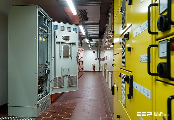 Case study: The magic I used to reduce harmonics in a plant (on photo: MR active filters; credit: REINHAUSEN GMBH)
Technical issues related to the high content of the fifth and seventh current harmonics are typical for electric motor control applications, where six pulse rectifiers are commonly used inside various types of motor drives.
This article will show how problems related to the high content of the fifth current harmonic can be significantly mitigated by the use of a passive harmonic filter.
Problem and solution will be represented in the form of a case study, including true data and measurements gained during the project I was involved in.
1. Basics about harmonic distortion
When the current or voltage signal is not of exact sinusoidal shape, we say that such a signal is distorted. Since we, as electrical engineers, are used to deal with sinusoidal AC signals, mathematical model has been created for representation of such distorted signal as the sum of several sinusoidal signals with different frequencies.
For that purpose, a Fourier transform is used.
For example, in 50 Hz systems, harmonic with the frequency of 250 Hz will be of fifth-order, since 250 divided by 50 equals 5.
In other direction, when we say “harmonic of seventh order” or just “seventh harmonic” that implies harmonic with the frequency of 350 Hz, since 50 multiplied by 7 equals 350.

As we said, total distorted current can be represented as the sum of current harmonics:

where in is nth harmonic of current, and DC component is neglected. The more harmonic we take into sum, the more accurate representation of real distorted current will be achieved.
Same expression for total current, only with RMS (Root Mean Square) values and frequencies shown, will be:

True RMS value of distorted current will be:

As a measure for quantity of distortion, THD (Total Harmonic Distortion) factor is used. In general, there are two formulas for calculation of this factor. First one uses true RMS value as a base for higher harmonics content definition:

As a reference for higher harmonics content definition, RMS value of first harmonic (fundamental) is used:
THD percent value calculated in this way may arise significantly above 100%. Percent value of harmonic content is ratio between RMS value of that particular harmonic, and RMS value of fundamental.
For example, if we say that seventh harmonic content is 11%, that means:

Distortion of current, i.e. current harmonics, will be created as a consequence of nonlinear consumers connection to power supply system. This type of consumers will generate distorted current even if supply voltage is perfectly sinusoidal.
Major problems caused by increased harmonic distortion are equipment and cable overload, excessive heating, nuisance tripping of protective devices, increased wear of circuit breakers and other switchgear, incorrect measurement, etc.
Related electrical guides & articles


Miodrag Kokotovic
Graduated from Faculty of Electrical Engineering, within University of Belgrade, in the field of electrical power systems. Expert in electrical part of tender preparation, design, procurement, construction and commissioning of treatment plants and pumping stations, electrical power quality and energy management.Profile: Miodrag Kokotovic
