
Estimated Study Time: 12 minutes
Design changes to reduce transformer losses
Design changes to reduce transformer losses, just as in a motor, always involve trade offs. For example, consider varying the cross-sectional area of the transformer core. An increase tends to lower no-load loss while raising the winding loss.
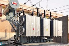
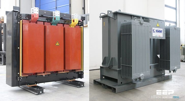 How to reduce transformer losses at design stage (photo credit: gbeonline.com)
An increase in volts per turn reduces winding loss while increasing the core loss.
To raise transformer efficiency, core loss has probably drawn the most attention. Core construction permits two important energy-saving features not applicable to industrial motors. First, the inherent colinearity between lamination orientation and the magnetic field direction allows use of grain oriented steel for transformer laminations.
That greatly reduces hysteresis loss in the core-the energy required to cyclically realign the “molecular magnets” within the steel, which are randomly positioned in a non-oriented material.
Second, because laminations are sheared or slit in strips rather than being punched with slots, much thinner material can be used in a transformer core than in a rotating machine. Whereas motor laminations are usually 0.014 to 0.025 inch thick, transformer lamination thickness may be as low as 0.006, with 0.009 to 0.012 being common. That lowers eddy current loss.
A further improvement appearing during the 1980’s is amorphous core material.
Resembling glass more than steel, this lamination material contains no granular structure at all. Laminations only 0.001 inch thick were used in the first mass-produced distribution transformers (25 kVA) manufactured by Westinghouse in 1986. Many similar units have been put in service since then, along with some large power transformers.
The design approaches for reduction of transformer losses are well known and proven. Generally they consists of the following:
- Using more material
- Better material
- New Material
- Improved distribution of materials
- Improvement in cooling medium and methods
Each design tries to achieve desired specifications with minimum cost of materials or minimum weight or volume or minimum overall cost of ownership. Worldwide, more and more consumers are now purchasing transformers based on the total ownership costs, than just the first cost.
Minimising Iron Losses
Losses in Core
Choice of metal is critical for transformer cores, and it’s important that good quality magnetic steel be used. There are many grades of steel that can be used for a transformer core. Each grade has an effect on efficiency on a per-kg basis. The choice depends on how you evaluate non-load transformer losses and total owning costs.
Almost all transformer manufacturers today use steel in their cores that provides low transformer losses due to the effects of magnetic hysteresis and eddy currents. To achieve these objectives, high permeability, cold-rolled, grain-oriented, silicon steel is almost always used. Construction of the core utilizes step lap mitered joints and the laminations are carefully stacked.
The evolution of materials used in transformer core is summarised below.
Table 1 – Evolution of core material
| Year (Approx.) | Core Material | Thickness (Mm) | Loss (W/Kg At 50hz) | |
| 1910 | Warm rolled FeSi | 0.35 | 2 | 1.5 T |
| 1950 | Cold rolled CRGO | 0.35 | 1 | 1.5 T |
| 1960 | Cold rolled CRGO | 0.3 | 0.9 | 1.5 T |
| 1965 | Cold rolled CRGO | 0.27 | 0.84 | 1.5 T |
| 1975 | Amorphous metal | 0.03 | 0.2 | 1.3 T |
| 1980 | Cold rolled CRGO | 0.23 | 0.75 | 1.5 T |
| 1985 | Cold rolled CRGO | 0.18 | 0.67 | 1.5 T |
There are two important core materials used in transformer manufacturing:
- Amorphous metal and
- CRGO (Cold Rolled Grain Oriented)
It can be seen that losses in amorphous metal core is less than 25% of that in CRGO. This material gives high permeability and is available in very thin formations (like ribbons) resulting in much less core losses than CRGO.
The trade off between the both types is interesting. The use of higher flux densities in CRGO (up to 1.5 T) results in higher core losses. However, less amount of copper winding is required, as the volume of core is less. This reduces the copper losses.
In amorphous core, the flux density is less and thinner laminations also help in reducing core losses. However, there is relatively a larger volume to be dealt with, resulting in longer turns of winding, i.e. higher resistance resulting in more copper losses. Thus iron losses depend upon the material and flux densities selected, but affect also the copper losses.
Amorphous cores
A new type of liquid-filled transformer introduced commercially in 1986 uses ultra low-loss cores made from amorphous metal. The core losses are between 60% to 70% lower than those for transformers using silicon steel. To date, these transformers have been designed for distribution operation primarily by electric utilities and use wound-cut cores of amorphous metal.
Their ratings range from 10kVA through 2500kVA.
The reason utilities purchase them, even though they are more expensive than silicon steel core transformers, is because of their high efficiency.
The use of amorphous core liquid-filled transformers is now being expanded for use in power applications for industrial and commercial installations. This is especially true in other countries such as Japan.
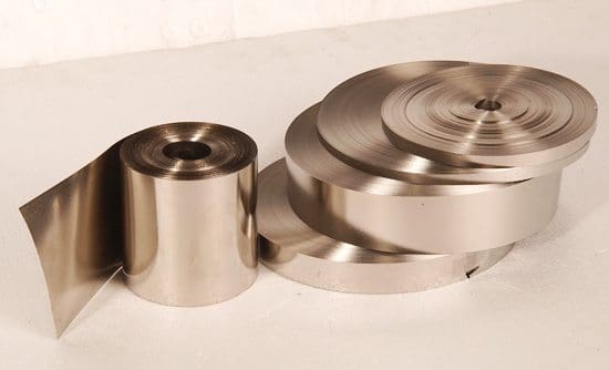
Amorphous metal is a new class of material having no crystalline formation. Conventional metals possess crystalline structures in which the atoms form an orderly, repeated, three-dimensional array. Amorphous metals are characterized by a random arrangement of their atoms (because the atomic structure resembles that of glass, the material is sometimes referred to as glassy metal).
This atomic structure, along with the difference in the composition and thickness of the metal, accounts for the very low hysteresis and eddy current losses in the new material.
Cost and manufacturing technique are the major obstacles for bringing to the market a broad assortment of amorphous core transformers. The price of these units typically ranges from 15% to 40% higher than that of silicon steel core transformers. To a degree, the price differential is dependent upon which grade of silicon steel the comparison is being made.
At present, amorphous cores are not being applied in dry-type transformers. However, there is continuous developmental work being done on amorphous core transformers, and the use of this special metal in dry-type transformers may become a practical reality sometime in the future.
If you’re considering the use of an amorphous core transformer, you should determine the economic trade off. In other words, the price of the unit versus the cost of transformer losses. Losses are especially important when transformers are lightly loaded, such as during the hours from about 9 p.m. to 6 a.m. When lightly loaded, the core loss becomes the largest component of a transformer’s total losses.
Thus, the cost of electric power at the location where such a transformer is contemplated is a very important factor in carrying out the economic analyses. Different manufacturers have different capabilities for producing amorphous cores, and recently, some have made substantial advances in making these cores for transformers.
The technical difficulties of constructing a core using amorphous steel have restricted the size of transformers using this material. The metal is not easily workable, being very hard and difficult to cut, thin and flimsy, and difficult to obtain in large sheets.
However, development of these types of transformers continues, you can expect units larger than 2500kVA being made in the future.
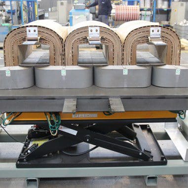
Minimising Copper losses
The major portion of copper losses is I2R losses. Using a thicker section of the conductor i.e. selecting a lower current density can reduce the basic I2R losses. However, an arbitrary increase in thickness can increase eddy current losses. In general, decreasing radial thickness by sectionalisation leads to reduction in eddy current losses. A properly configured foil winding is useful in this context.
All the same, designers can always try to get minimum basic I2R and minimum eddy current losses for a given design and specified harmonic loading.
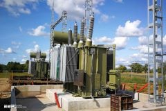
Right choice of liquid-filled or dry type
Information on the pros and cons of the available types of transformers frequently varies depending upon what information is made available by the manufacturer. Nevertheless, there are certain performance and application characteristics that are almost universally accepted.
Basically, there are two types of transformers: Liquid insulated and cooled (liquid-filled type) and non liquid insulated, air or air/gas cooled (dry type). Also, there are subcategories of each main type.
As this topic has been already covered in this technical article, feel free to read there more about choosing the right transformer type.
Reference // Best Practice Manual for transformers – Devki Energy Consultancy Pvt.
Related electrical guides & articles


Edvard Csanyi
Hi, I'm an electrical engineer, programmer and founder of EEP - Electrical Engineering Portal. I worked twelve years at Schneider Electric in the position of technical support for low- and medium-voltage projects and the design of busbar trunking systems.I'm highly specialized in the design of LV/MV switchgear and low-voltage, high-power busbar trunking (<6300A) in substations, commercial buildings and industry facilities. I'm also a professional in AutoCAD programming.
Profile: Edvard Csanyi
