The need for redundancy
Generally speaking, distribution substations should be designed with redundancy allowing a portion of feeders to remain energized if any major component fails or is taken out of service for maintenance.
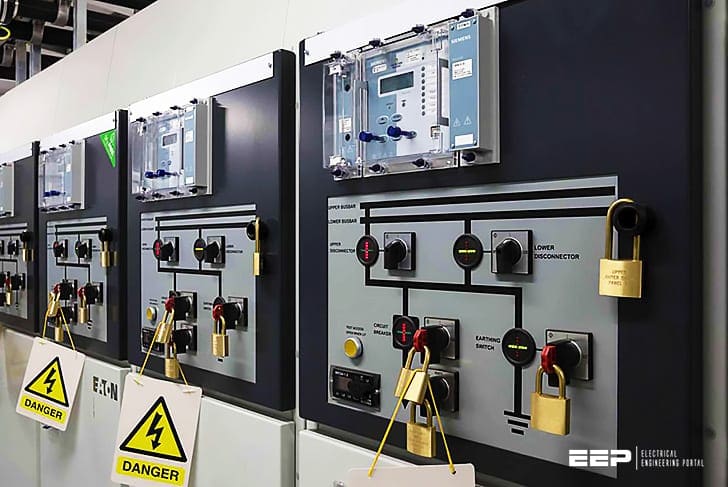
To help ensure a reliable system, planners and operators and engineers prefer having as much redundancy in these components as can be justified economically.
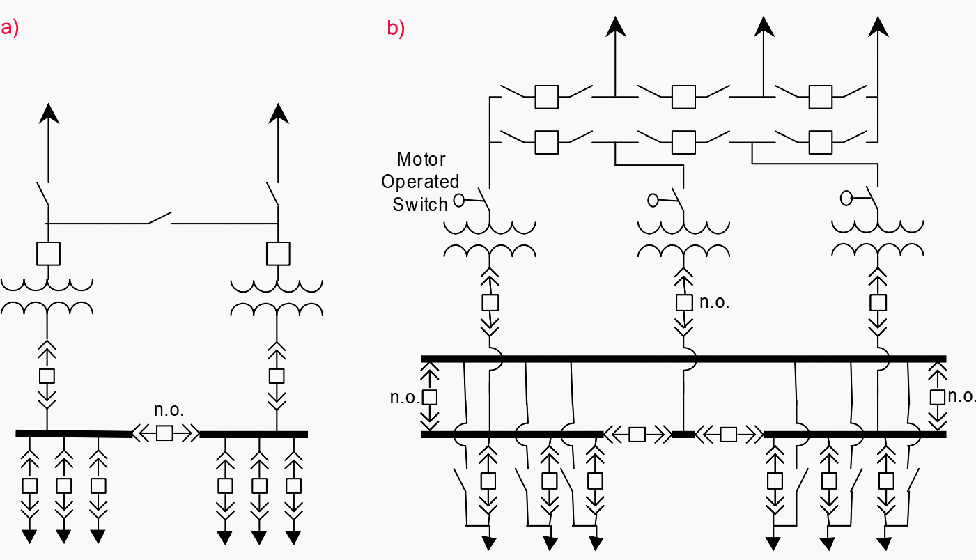
Figure 1 shows a common substation layout to the left and a much more complicated (and reliable) substation to the right (“n.o.” refers to a normally open switch). The substation to the left is sometimes referred to as an “H-station” or a “transmission loop-through” design.
The substation to the right further increases reliability by having an additional transmission line, an energized spare power transformer, primary ring-bus protection, motor-operated switches, and a secondary transfer bus.
The concept of redundancy in technical terms is tied to the statistical one of a reduction in the probability of unavailability.

Redundancy means the existence of one or more components, of one or more circuits, being able, in replacement of homologous parts of a system, to assume their functions totally or partially.
Let’s consider a double radial system supplied by the public grid through one medium voltage line only. The question is whether the main switchboard must be made of two sections or if one section only is sufficient. The answer requires an evaluation of the reliability of the switchboard compared to the supply availability:
How many times a year can the switchboard be unavailable due to faults, maintenance, modifications?
If the answer is mostly favorable for the supply availability and therefore negative for the switchboard, the subdivision of its busbars into two separate sections can be justified.
In a different case the switchboard can be defined as infallible compared to supply and the type with a simple busbar can be correctly chosen.
It is important to remember that up to now reference has been made implicitly to alternative activated functions, i.e. those that can be made operative by a normal manual or an automatic action.
Independence of redundant parts
In the concept of redundancy it is fundamental for the redundant parts to be ‘independent’ of one another. The degree of independence cannot be defined in general, but has to be evaluated, case by case, with regard to the function of the part under examination and to the service conditions.
The following examples aim to clarify the concept of independence:
Example #1
An MV switchboard with a double system of busbars, with a degree of independence according to the following situations:
Situation #1
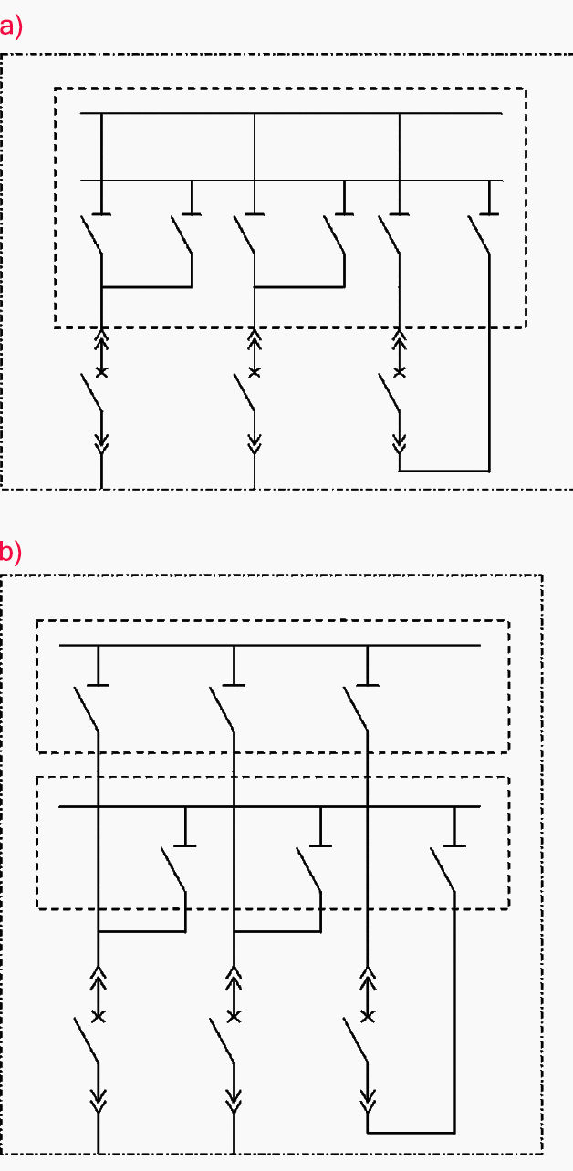
The two busbar systems are disposed adjacently and side by side within a protected switchboard without any segregation.
They are independent only in relation to ordinary operation, for the possibility to effect different services on each in turn, but not in relation to faults on the busbars or on the disconnecting switches against the busbars, at maintenance or on repair (Figure 2a).

Situation #2
The two busbar systems, adjacent and side by side as above, are disposed, with their switches, within compartments segregated metallically and made short-circuit tight (Figure 2b).
They can be considered as independent for determined maintenance and repair operations and for faults concerning one system of busbars only, but not for faults that concern disconnecting switches against the busbar or that, because of the emission of corrosive smoke, can deteriorate contacts.
Situation #3
Description: The two busbar systems are set out within the switchboard as a simple busbar (Figure 3) with the two sections set in line and with a tie breaker being the only common part to the switchboard.
The independence of the two sections depends on the measures taken to prevent propagation of a section fault into the other through the
tie-breaker unit.


Situation #4
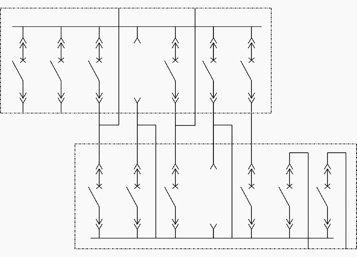
Description: The two busbar systems are in two completely separate switchboards (double switchboard, scheme with two switches, Figure 4) put at a safe distance in case of fire, or even in different rooms (fireproof compartments); independence is exte nded to all the conditions considered above.
Example #2
Description: Two lines in cables with separate ways and such that the fault of one line cannot compromise the functionality of the other.
In the examples shown the common container is the switchboard with more or less effective insulation, but also the room is a container for more switchboards and, in the case of fire, independence can be compromised.

The analysis of independence becomes complicated when passing from consideration of the power circuits to protection and control systems, i.e. sources and supply circuits, circuits, devices.
The independence of alternative parts comprising a redundant system can never be absolute and total, unless they are completely separate and autonomous from supply up to the final user, including the respective control systems.
In all other cases there are contact points, both for power circuits and for protection and control systems.
This is the reason why in the schemes with a double switchboard and double switch (Figure 4) the disconnector is also doubled.
The study of the control systems of the tie breaker requires particular attention to keep the independence level as high as possible.
Sources:
- Handbook of Power Quality – Angelo Baggini
- Electric Power Distribution Reliability – Richard E. Brown
Copyright Notice
This technical article is protected by U.S. and international copyright laws. Reproduction and distribution of PDF version of this technical article to websites such as Linkedin, Scribd, Facebook and others without written permission of the sponsor is illegal and strictly prohibited.© EEP-Electrical Engineering Portal.
Related electrical guides & articles
Premium Membership
Edvard Csanyi
Hi, I'm an electrical engineer, programmer and founder of EEP - Electrical Engineering Portal. I worked twelve years at Schneider Electric in the position of technical support for low- and medium-voltage projects and the design of busbar trunking systems.I'm highly specialized in the design of LV/MV switchgear and low-voltage, high-power busbar trunking (<6300A) in substations, commercial buildings and industry facilities. I'm also a professional in AutoCAD programming.
Profile: Edvard Csanyi







The Article The concept of redundancy in the Power Circuits is realy amazing. How I can download?
Dear
What are the systems , which you call redundancy , like sieges S71500 and or S7400 ?? do they have both redundancy ??
does Hitachi company has same kind of product?
your info will be highly appreciated
Best Regards
I just wish thay more of these articles could be availed without restriction to premium users alone.
Thanks for the little shared for basic users.