


Estimated Study Time: 49 minutes
Schematics for Power Generation Project
This technical article provides an in-depth technical analysis of the Relay and Metering Panel schematics, examining the attached engineering panel design document (PDF). The panel which we’ll discuss in great detail, serves as the central command node for electrical protection, real-time power metering, and critical fault annunciation.
 Analysis of the Relay and Metering Panel Schematics (PDF)
The panel integrates advanced numerical protection algorithms with robust electromechanical tripping matrices.
The article methodically deconstructs the schematic sheets, detailing the logic, component application, and wiring topology of the AC and DC auxiliary systems, the primary Generator Protection Relay (GPR), the redundant master tripping architectures, and the associated metering circuits.
The complete 57-page PDF document containing the Relay and Metering Panel schematics for the 1×8.6 MW power generation project is available for download below. Please open the file to reference alongside the following technical discussion.
… and not to forget, get yourself a big cup of coffee!
- Project Specifications and General Arrangement
- Standardized Symbology and Wiring Protocols
- AC Auxiliary Systems:
- DC Power Supply and Supervision:
- Uninterruptible Power Supply (UPS) Network
- Instrument Transformer Interfacing and Shorting Topologies:
- Generator Protection Relay (GPR) Analog Injection:
- Generator Protection Relay (GPR) Binary Input Architecture
- Generator Protection Relay (GPR) Binary Output Architecture
- Rotor Earth Fault Module Circuit Integration
- Logical Trip Matrix and Human-Machine Interface (HMI) Topography
- 86A and 86B Master Trip Electromechanical Circuitry
- Execution of Closing and Tripping Commands
- Auxiliary Signal Multiplication and Breaker Failure Logic:
- The Annunciation Subsystem
- Metering Instrumentation and Power Quality Analysis
- Terminal Arrangements and External Interfacing Architecture
- Bill of Materials (BOM) Specifications
- Summary
- Attachment (PDF) 🔗 Digital Power System Protection Guide For Final Year Undergraduate and Postgraduate Students
1. Project Specifications and General Arrangement
The foundational parameters of the relay and metering panel are dictated by the generator specifications detailed on the Name Plate Details (Sheet 008, Row C, Columns 10-15). The synchronous generator possesses a continuous rating of 8.6 Megawatts (MW) operating at a nominal frequency of 50 Hertz (Hz) and a rated power factor of 0.80 lagging.
The primary sensing elements comprise Potential Transformers (PTs) with a primary rating of 11,000 Volts (V) and a secondary output of 110 V, alongside Current Transformers (CTs) rated for a 700 Amperes (A) primary and a 1 A secondary current.
The enclosure provides an Ingress Protection rating of IP4X, making it suitable for standard indoor operational environments.
Figure 1 – Figure 1 – Physical construction and layout of the panel (Sheet 005)
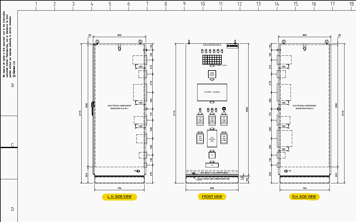
The front elevation (Sheet 005, Row C, Column 5) reveals the flush-mounted interface devices, including the Annunciator (MBAS 0600), the Power Quality Meter (Satec PM135EH), and designated test terminal blocks.
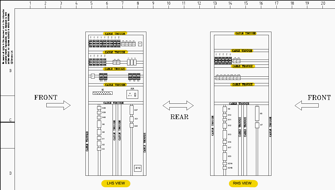
The internal general arrangement (Sheet 007, Row A to D, Columns 1-20) details a highly organized mounting plate structure utilizing FR PVC wire ducts (cable troughs) to separate field wiring and internal control signal routing.
Internal components, such as Miniature Circuit Breakers (MCBs), auxiliary relays, and terminal blocks (X1 through X40), are mounted to standard DIN rails across multiple elevations.
Figure 2 – Internal panel arrangement and wiring (Sheet 007)
2. Standardized Symbology and Wiring Protocols
To interpret the schematic diagrams accurately, Sheet 003 provides the normative legends and symbols. A panel space heater is depicted as a resistive element, utilized to prevent internal condensation.
Electromagnetic actuators (contactors or auxiliary relays) operating on Direct Current (DC) are shown with integrated surge protection (freewheeling diodes or varistors) across their coils (e.g., Row C, Column 13) to suppress high-voltage inductive transients during de-energization.
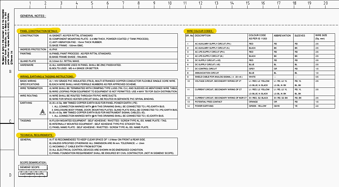
Wiring execution strictly adheres to the color-coding standards specified on Sheet 009 (Row B, Columns 1-10).
- AC Auxiliary Supply phases are wired with Red (2.5 mm2), while the neutral utilizes Black (2.5 mm2).
- DC control circuits employ Grey wiring (1.5 mm2).
- Voltage and current secondary circuits from instrument transformers use phase-specific colors: Red (L1), Yellow (L2), Blue (L3), and Black (Neutral) with 2.5 mm2 cross-sections.
- The protective earth (PE) and instrument earth (IE) networks rely on Green-Yellow multi-stranded flexible copper conductors (4.0 mm2), connecting to a 25 x 6 mm tinned copper earth bus.
Figure 3 – Panel wiring protocols and colors (Sheet 009)
3. AC Auxiliary Systems
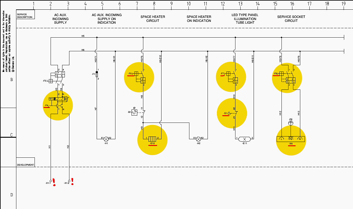
The AC auxiliary supply infrastructure provides power to environmental controls, illumination, and non-critical peripheral systems within the enclosure. As documented on Sheet 010 (Row A to D, Columns 1-20), the 230 V AC single-phase supply enters through terminal block X1 (terminals 1 and 2), located at Row D, Columns 2-3.
The primary isolation and earth-leakage protection are achieved via a 2-pole, 25 A RCCB designated as F4, which features a 30 mA trip threshold (Sheet 010, Row B, Column 3). This ensures immediate disconnection in the event of an insulation failure, protecting operating personnel from electrical shock.
3.1 Space Heater Circuit:
MCB F6 (1-pole, 6 A, C-Curve) protects the 100 W anti-condensation space heater (E12), depicted at Sheet 010, Row C, Column 9. The heater’s operation is dynamically controlled by a series-connected thermostat (B1), set to 35°C during Factory Acceptance Testing (FAT).
This thermal management prevents the ambient internal temperature from dropping below the dew point, thereby preventing moisture accumulation on sensitive printed circuit boards within the protective relays.
An indicating lamp (H2) illuminates when the heater circuit is active.
3.2 Illumination Circuit:
MCB F7 (1-pole, 6 A, C-Curve) supplies the LED tube light (E11), located at Sheet 010, Row C, Column 14. A door-actuated limit switch (S1) is integrated into this circuit, ensuring the luminaire is automatically energized exclusively when the rear panel door is opened for maintenance.
3.3 Service Receptacle:
MCB F8 (2-pole, 6 A, C-Curve) isolates the universal service socket (XA), providing a localized 230 V AC source for diagnostic equipment, laptops, or secondary testing apparatus (Sheet 010, Row C, Column 18).
Figure 4 – AC Auxiliary Systems (Sheet 010)
4. DC Power Supply and Supervision
The 110 V DC network forms the critical operational backbone of the protection scheme, powering the numerical relays, tripping matrices, and primary switchgear coils.
4.1 Incoming Supply and Primary Isolation:
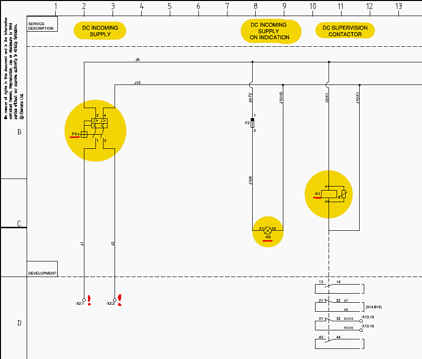
Analyzed on Sheet 011, the 110 V DC supply enters via terminal block X2 (terminals 1 and 2) at Row D, Column 2. It passes through the primary DC ON/OFF MCB (F9), a 2-pole, 16 A device configured with a C-Curve tripping characteristic (Sheet 011, Row B, Column 3).
An indicating lamp (H3) provides visual confirmation of incoming DC presence.
4.2 DC Supervision Logic:
A continuous monitoring topology is established using supervision contactor K1 (Sheet 011, Row C, Column 11). The coil of K1 is continuously energized as long as the 110 V DC bus remains healthy. If the DC voltage collapses or MCB F9 opens, K1 de-energizes.
The downstream distribution of the 110 V DC supply is exhaustively segmented to isolate sub-system faults, preventing a single short circuit from disabling the entire protection scheme. This distribution is documented across Sheets 012 and 013.
Figure 5 – Incoming Supply and Primary Isolation
4.3 Protection Subsystems:
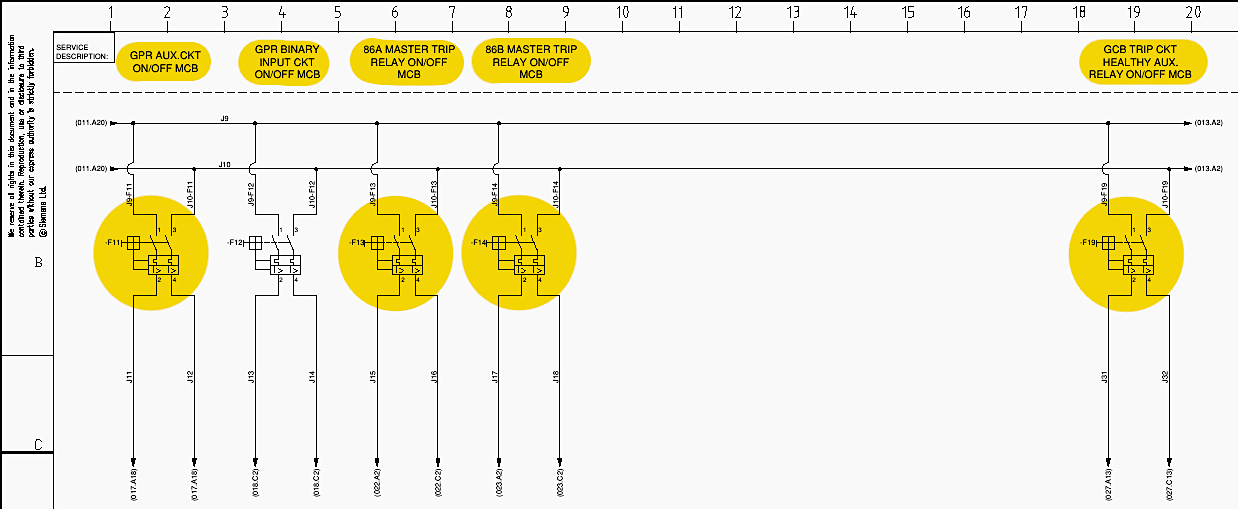
F11 (2-pole, 2 A) dedicatedly powers the internal power supply module of the Generator Protection Relay (GPR). F12 (2-pole, 6 A) provides the wetting voltage for the Binary Inputs of the GPR.
4.4 Trip Relays:
F13 (2-pole, 6 A) and F14 (2-pole, 6 A) independently supply the 86A and 86B Master Trip Relays, respectively (Sheet 012, Row B, Columns 8-11). This bifurcation ensures that the failure of one tripping path does not compromise the redundant tripping architecture.
4.5 Auxiliary Functions:
F19 supplies the Generator Circuit Breaker (GCB) Trip Circuit Healthy monitoring relay. F20 supplies the 50BF (Breaker Failure) auxiliary relay. F21, F22, and F23 respectively power the Annunciator, the Mega-Watt Transducer (MW-TDR), and the active metering circuits (Sheet 013, Row B).
Figure 6 – DC power distribution circuits
5. Uninterruptible Power Supply (UPS) Network
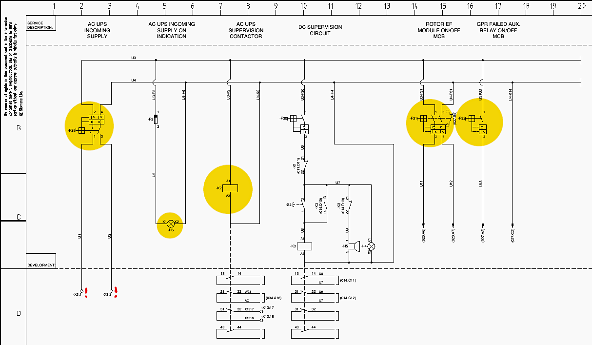
Certain critical components require a stabilized 230 V AC supply immune to transient station grid collapses. As detailed on Sheet 014, the AC UPS incoming supply routes through terminals X3:1 and X3:2 (Row D, Column 3) into MCB F29 (2-pole, 16 A).
Similar to the DC wiring, the UPS integrity is continuously monitored by contactor K2 (Sheet 014, Row C, Column 7).
MCB F32 (1-pole, 6 A) supplies the GPR Failed auxiliary relay (K14), executing a fail-safe logic operation.
Figure 7 – AC UPS and DC supervision circuit
6. Instrument Transformer Interfacing and Shorting Topologies
The accurate translation of primary high-voltage and high-current signals into logic-level secondary signals is mediated through specialized terminal blocks equipped with safety mechanisms. Sheet 016 outlines these interfaces.
6.1 Current Transformer (CT) Circuits:
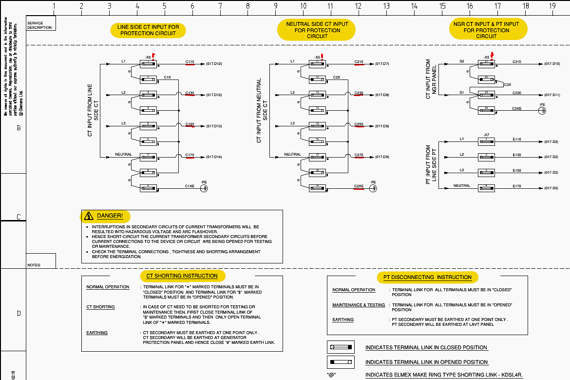
The CT secondary circuits must never be open-circuited while the primary conductor is energized, as this generates lethal and destructive voltages due to unconstrained magnetic flux. The schematic specifically highlights this hazard with a “DANGER!” decal (Sheet 016, Row D, Columns 3-9), mandating that secondary circuits be short-circuited before any device disconnection.
The line-side CT inputs interface at terminal block X5 using Elmex KDSL4R ring-type shorting links (Sheet 016, Row A, Columns 4-7). The phase currents arrive at terminals C110 (L1), C130 (L2), and C150 (L3), with the common neutral at C170.
Crucially, the schematic mandates single-point earthing for CT secondaries to prevent circulating ground currents that could induce measurement errors. The earth link (designated with a “#” symbol) is explicitly closed at the generator protection panel.
Figure 8 – Current Transformer (CT) Circuits
6.2 Potential Transformer (PT) Circuits:
Unlike CTs, PT secondaries must never be short-circuited, as this mimics a zero-impedance fault. The PT signals from the line side arrive at terminal block X7 (L1: E110, L2: E130, L3: E150, Neutral: E170), utilizing standard disconnecting links designed for safe isolation during relay calibration (Sheet 016, Row B, Columns 14-17).
7. Generator Protection Relay (GPR) Analog Injection
The analog signals derived from the instrument transformers are directly injected into the Generator Protection Relay, designated as K4, which is specified as a Siemens SIPROTEC 7UM622 series numerical relay (Sheet 017).
7.1 Differential Protection (87G) Analog Paths:
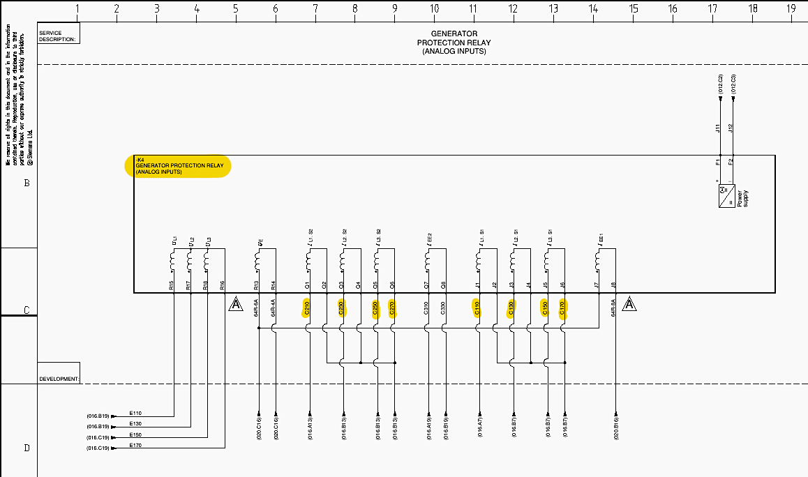
The numerical relay calculates the vector difference between the line-side and neutral-side currents to detect internal stator faults. The line-side currents (C110, C130, C150, C170) enter the GPR at analog ports J1-J6 (Sheet 017, Row C, Columns 11-14).
The neutral-side currents (C210, C230, C250, C270) enter at ports Q1-Q6 (Sheet 017, Row A, Columns 6-9).
7.2 Voltage Analog Paths:
The line-side PT voltages (E110, E130, E150) enter the voltage measuring inputs of the GPR (U1, U2, U3) to enable impedance, over/undervoltage, and directional power algorithms (Sheet 017, Row C, Columns 3-5).
7.3 Specialized Analog Paths:
The NGR CT input (C310, C330) is routed to the sensitive earth fault input (IN3) for 50N/51N protection. Additionally, the measurement signals from the external Rotor Earth Fault coupling unit enter at measuring inputs 64R-8A, 64R-6A, and 64R-4A (Sheet 017, Row B, Columns 16-18).
Figure 9 – Generator Protection Relay (GPR) Analog Input Circuit
8. Generator Protection Relay (GPR) Binary Input Architecture
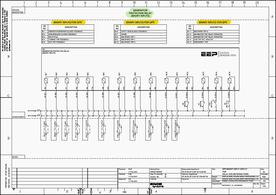
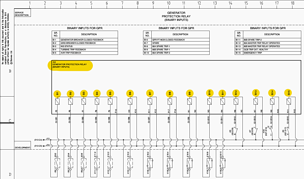
Binary Inputs (BIs) serve as the sensory apparatus for the numerical relay, allowing it to interpret external mechanical and electrical statuses, integrating them into its internal Boolean logic matrices. The GPR (K4) is equipped with 15 distinct Binary Inputs, meticulously detailed on Sheet 018. The 110 V DC wetting voltage (+ve) is routed through MCB F12, passing through terminal block X9 and distributed across the field contacts.
When a field contact closes, it returns the positive potential to the specific BI port on the GPR, completing the circuit to the negative DC bus.
The functional assignments of the Binary Inputs (Sheet 018, Row B to D, Columns 1-20) are as follows:
- BI-1 (G1-B11): Generator Breaker Closed Feedback. Essential for internal relay logic to determine whether the generator is synchronized to the grid, enabling specific operational protections (e.g., Reverse Power 32R).
- BI-2 (G1-B12): Grid Breaker Closed Feedback. Utilized for system condition monitoring and interlocking logic.
- BI-3 (G1-B13): NIS (Network Interconnection System) Status.
- BI-4 (G1-B14): Turbine Trip Feedback. Informs the electrical protection relay that the prime mover’s mechanical protection has operated, initiating sequential electrical decoupling.
- BI-5 (G1-B15): Automatic Voltage Regulator (AVR) Trip Feedback. Alerts the GPR to an excitation system failure.
- BI-6 (G1-B16): GPR PT MCB Closed Feedback. A critical input that blocks false voltage-dependent trips (such as Undervoltage 27) if the sensing PT circuit breaker has been manually opened or tripped.
- BI-7 (G1-B17): Configured as a spare input for future expansion.
- BI-8 (G1-B18) & BI-9 (G1-B19): Designated for 86A and 86B Spare Trip-1 functions, allowing external devices to leverage the GPR’s tripping matrix.
- BI-10 (G1-B110) & BI-11 (G1-B111): Designated for 86A and 86B Spare Trip-2 functions.
- BI-12 (G1-B112) & BI-13 (G1-B113): 86A and 86B Master Trip Relay Operated feedbacks. These confirm to the GPR that its trip command successfully actuated the electromechanical lockout relays.
- BI-14 (G1-B114): GCB Trip Circuit Healthy. Ensures the primary circuit breaker’s trip coil has continuity.
- BI-15 (G1-B115): Emergency Trip input, allowing a manual, localized emergency push button to directly initiate the numerical relay’s trip sequence.
Figure 10 – Generator Protection Relay (GPR) Binary Inputs
9. Generator Protection Relay (GPR) Binary Output Architecture
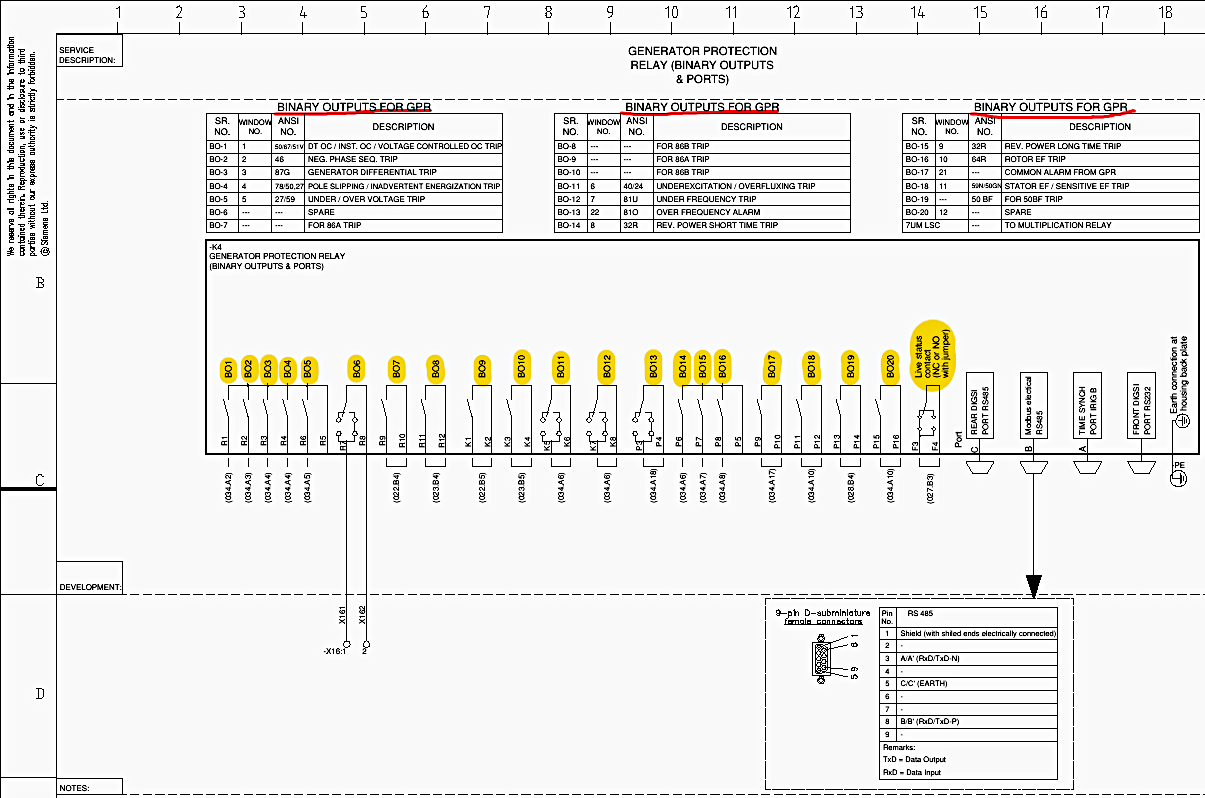
Binary Outputs (BOs) form the actuation layer, translating internal algorithmic trip decisions into physical contact closures that execute mechanical and electrical isolation. Sheet 019 delineates the assignment of the 20 Binary Outputs of the 7UM622 relay. The relay outputs rely on the DC control voltage, executing circuit closures based on configured fault parameters.
The functional assignments (Sheet 019, Row B to D, Columns 1-17) are mapped to specific ANSI device numbers:
- BO-1: Actuates upon Overcurrent (50/51) or Voltage Controlled Overcurrent (51V) conditions.
- BO-2: Actuates upon Negative Phase Sequence (46) detection, preventing rotor overheating due to asymmetrical stator currents.
- BO-3: Actuates upon Generator Differential (87G) fault detection, signaling severe internal stator winding short circuits.
- BO-4: Assigned to Pole Slipping (78) or Inadvertent Energization (50/27) conditions, protecting against destructive electromechanical torque oscillations.
- BO-5: Actuates for Under/Over Voltage (27/59) excursions.
- BO-6: Configured as a spare.
- BO-7, BO-9: High-speed signaling contacts assigned directly to the 86A Master Trip Relay coil.
- BO-8, BO-10: High-speed signaling contacts assigned directly to the 86B Master Trip Relay coil.
- BO-11: Actuates upon Underexcitation (40) or Overfluxing (24) anomalies, protecting the core magnetic integrity.
- BO-12: Actuates upon Under Frequency (81U) conditions.
- BO-13: Dedicated to Over Frequency (81O) alarm signaling.
- BO-14: Initiates a Reverse Power Short Time Trip (32R), operating when the generator begins motoring, absorbing active power from the grid.
- BO-15: Initiates a Reverse Power Long Time Trip (32R).
- BO-16: Actuates upon Rotor Earth Fault (64R) tripping.
- BO-17: Configured as a consolidated Common Alarm output from the GPR.
- BO-18: Actuates upon Stator Earth Fault or Sensitive Earth Fault (50N/51N) detection.
- BO-19: Serves as the initiation contact for the Breaker Failure (50BF) sequence.
- BO-20: Configured as a spare.
- Life Status Contact (LSC): Failsafe contact (normally closed or normally open depending on jumper configuration) that changes state if the numerical relay experiences an internal hardware or software watchdog failure, routing to the GPR Fail multiplication circuit.
An IRIG-B port is also present for microsecond-level time synchronization across the substation.
Figure 11 – Generator Protection Relay (GPR) Binary Outputs
10. Rotor Earth Fault Module Circuit Integration
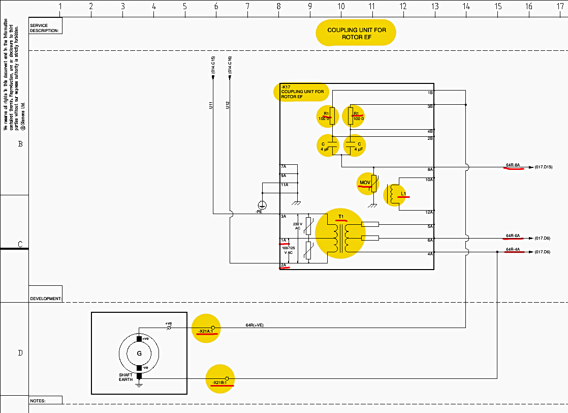
Rotor winding earth faults require specialized detection methodology because the field winding is an ungrounded DC circuit. Standard residual current techniques are ineffective. Sheet 020 describes the implementation of a separate Coupling Unit (K17, Siemens 7XR8100-0CA00) designed specifically for this purpose.
The coupling unit operates on a 230 V AC supply across terminals 1A and 2A, transforming and isolating the voltage via an internal transformer (T1) (Sheet 020, Row C, Column 10).
The unit injects an active, low-frequency AC voltage into the generator rotor circuit. The positive field terminal connects through terminal block X21A to coupling unit terminal 1B. The generator shaft earth return connects through terminal block X21B to coupling unit terminal 3B.
This leakage current is proportionally converted into a measurement signal output across terminals 6A and 4A, which is directly injected into the GPR analog inputs 64R-6A and 64R-4A for threshold evaluation by the numerical algorithms.
Figure 12 – Rotor Earth Fault Module Circuit
11. Logical Trip Matrix and Human-Machine Interface (HMI) Topography
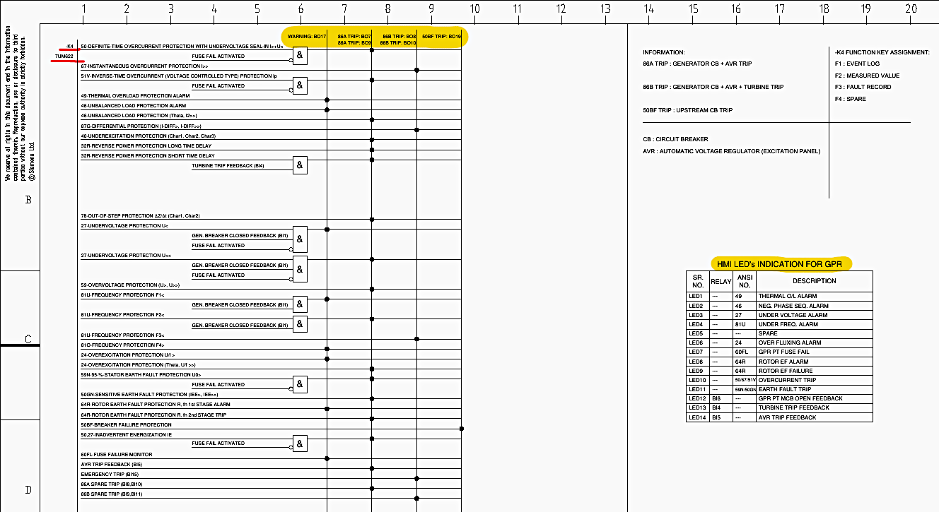
The translation of protective functions into defined action pathways is documented in the GPR Trip Matrix & HMI LED Indication schedule on Sheet 021. This matrix represents the internal software configuration of the 7UM622 relay, dictating exactly which physical outputs trigger upon the assertion of specific internal algorithms.
The tripping philosophy employs two redundant master trip relays (86A and 86B) to guarantee fault clearance even if one electromechanical path fails.
11.1 86A Trip Routing:
Configured to trip the Generator Circuit Breaker (GCB) and the Automatic Voltage Regulator (AVR). This isolates the generator from the grid and suppresses the field excitation, effectively neutralizing the electrical fault contribution.
11.2 86B Trip Routing:
Configured for comprehensive shutdown, tripping the GCB, the AVR, and issuing a direct trip command to the mechanical Turbine (prime mover).
Good Reading – 132/33kV, 31.5MVA Transformer Protection Schematics (PDF)
11.3 50BF Trip Routing
If the GCB fails to open upon command, this routes a trip to the upstream (grid side) circuit breakers to clear the fault.
The specific Boolean mappings (Sheet 021, Row A to D, Columns 1-20) indicate that critical internal faults such as Differential (87G) and Overcurrent (51V, 67) route to BOTH 86A (via BO7) and 86B (via BO8), ensuring absolute redundancy.
The “Fuse Fail Activated” logic state (derived from the 60FL function) is utilized to block voltage-dependent functions like Undervoltage (27) to prevent false tripping if the PT secondary circuit is compromised.
The relay’s frontal HMI provides rapid visual diagnostics via 14 configurable LEDs. The mapping dictates that LED1 illuminates for Thermal Overload Alarms (49), LED3 for Undervoltage Alarms (27), LED10 for Overcurrent Trips, and LED11 for Earth Fault Trips (59N/50GN). LED13 and LED14 provide visual confirmation of external mechanical trips (Turbine Trip and AVR Trip, respectively).
The function keys on the relay are programmed for operator convenience: F1 displays the Event Log, F2 displays Measured Values, and F3 displays the Fault Record (Sheet 021, Row C, Columns 14-17).
Figure 13 – Logical Trip Matrix and Human-Machine Interface (HMI)
12. 86A and 86B Master Trip Electromechanical Circuitry
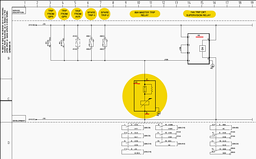
The physical realization of the tripping matrix involves the employment of robust, high-speed electromechanical lockout relays. The circuits for the 86A and 86B master trip relays are detailed on Sheets 022 and 023, respectively.
12.1 86A Trip Circuit (Sheet 022)
The core component is the K5 Master Trip Relay, an ABB PQA type device featuring 5 normally open and 2 normally closed contacts (Sheet 022, Row C, Column 10). The operating coil of K5 spans across the 110 V DC positive and negative buses. The positive activation signal can originate from several parallel paths: a trip from the GPR (BO7), a trip from the AVR panel, or external Spare Trip inputs (X20:1, X20:3).
When any of these parallel contacts close, the 110 V DC potential is applied across the K5 coil (terminals ‘a’ and ‘b’), causing it to actuate and mechanically latch into the operated state. The relay must be manually or electrically reset following a fault.
The auxiliary contacts of K6 then trigger an alarm in the Annunciator panel, warning operators of a compromised protection path before an actual fault occurs.
Further Study – Mastering DC supply selection schemes for HV control and protection panels
Mastering DC supply selection schemes for HV control and protection panels
12.2 86B Trip Circuit (Sheet 023)
Mirroring the 86A architecture for redundancy, the 86B circuit employs the K7 Master Trip Relay (ABB PQA type) located at Sheet 023, Row C, Column 10. The parallel actuation paths include the GPR trip (BO8), a localized Emergency Trip Push Button (S3), and distinct Spare Trip inputs (X20:11, X20:13).
The coil integrity of K7 is continuously monitored by the 74B Trip Circuit Supervision Relay (K8) operating on identical principles to K6.
Figure 14 – 86A Master Trip Electromechanical Circuitry (Sheet 022)
13. Execution of Closing and Tripping Commands
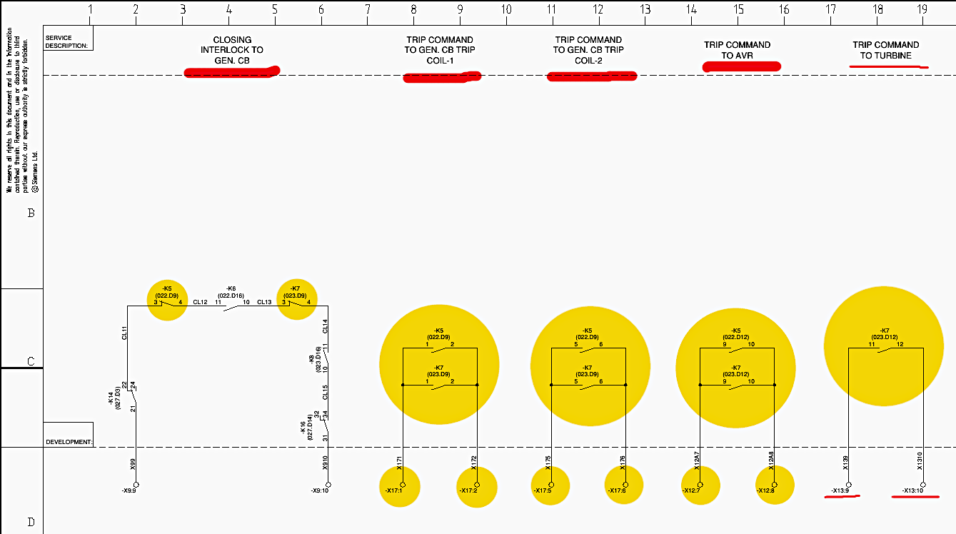
The translation of the Master Trip Relay states into actual circuit breaker manipulation is illustrated on Sheet 025. This sheet maps the complex interlocking required to safely operate the primary switchgear.
13.1 Closing Interlock
The Generator Circuit Breaker can only be closed manually or via synchronization systems if both Master Trip Relays are in their reset (healthy) state. The closing circuit routes the positive DC command through the normally closed contacts of K5 and K7 in series (Sheet 025, Row C, Columns 2 and 6).
If either 86A or 86B is in a tripped state, the closing circuit is physically broken, preventing the operator from closing the generator breaker onto an existing fault.
13.2 Trip Command Execution
The normally open contacts of K5 and K7 are utilized to execute the high-power trip commands.
13.3 Generator CB Trip Coil-1
A parallel arrangement of K5 and K7 contacts sends a direct positive DC pulse via terminals X17:1 and X17:2 to the primary trip coil of the generator breaker (Sheet 025, Row C, Columns 8-19).
13.4 Generator CB Trip Coil-2
A redundant, parallel arrangement of K5 and K7 contacts sends an identical pulse via X17:5 and X17:6 to the secondary trip coil of the generator breaker (Sheet 025, Row D, Columns 10-12). This dual-coil architecture ensures breaker opening even if one coil mechanism fails mechanically or electrically.
13.5 AVR Trip
Contact K5 routes a trip command via X12:7 and X12:8 to the automatic voltage regulator to rapidly de-excite the field.
13.6 Turbine Trip
Contact K7 independently routes a trip command via X13:9 and X13:10 to the turbine governor to halt steam or fuel flow.
Figure 15 – Closing and Tripping Command From 86A and 86B (Sheet 025)
14. Auxiliary Signal Multiplication and Breaker Failure Logic
Certain critical states must be transmitted to multiple discrete systems (such as the DCS, Annunciator, and external panels) simultaneously. To prevent overloading the numerical relay’s internal contacts and to provide galvanic isolation, signal multiplication circuits are employed on Sheet 027.
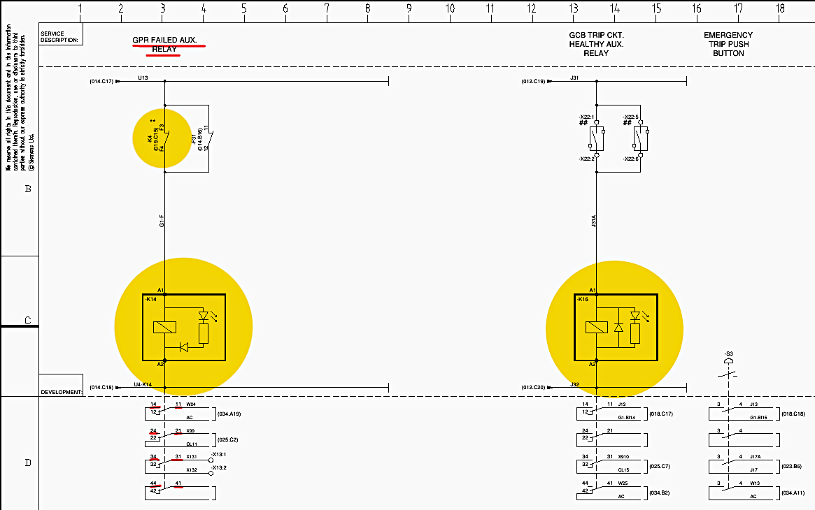
14.1 GPR Failed Auxiliary Relay:
The Life Status Contact of the GPR (K4) is wired in series with the 230 V AC supply to energize the K14 auxiliary relay (Sheet 027, Row B, Column 3). The note specifies that the GPR fail contact status is normally OPEN when the relay is healthy.
If the relay experiences a catastrophic internal fault, the contact closes, energizing K14. K14 utilizes its multiple contacts (11-14, 21-24, 31-34, 41-44) to simultaneously broadcast this failure to the Annunciator, the DCS, and other interlocking schemes (Sheet 027, Row D, Columns 2-5).
14.2 GCB Trip Circuit Healthy Auxiliary Relay:
Similarly, the external feedback confirming the integrity of the generator breaker’s trip coil is multiplied via auxiliary relay K16 (Sheet 027, Row C, Column 14). The relay is energized with 110 V DC when the trip circuit is healthy (status 1). Its multiple contacts distribute this status to the GPR binary input, the DCS, and the Annunciator.
14.3 Breaker Failure (50BF) Logic:
If a protective trip is initiated by the GPR, but the Generator Circuit Breaker physically jams or fails to extinguish the arc, the fault remains connected to the system. To mitigate this catastrophic scenario, the 50BF logic is utilized (Sheet 028). The GPR initiates the 50BF sequence via BO19.
This output energizes the K23 auxiliary relay (Sheet 028, Row C, Column 10). K23 acts as a powerful multiplication multiplier, utilizing its 7 normally open contacts to send retrip commands to the local breaker, initiate inter-tripping to upstream grid breakers via terminal block X31, and alert the Annunciator (Window 14).
Figure 16 – GPR Fail Multiplication Circuit (Sheet 027)
15. The Annunciation Subsystem
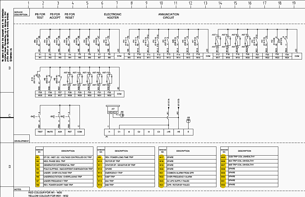
The visual and auditory alarm interface for control room operators is centered around the Minilec MBAS 0600 Annunciator (P1), detailed on Sheet 034. This device features a 32-window matrix (30×30 mm window size). The input logic relies on negative DC potential; when a field contact closes, it connects the window input terminal (W1 through W32) to the DC common line, triggering the alarm sequence.
The annunciation logic incorporates a dynamic electronic hooter (H7) that operates on 110 V DC and produces three selectable distinct tones depending on the severity of the fault (Sheet 034, Row D, Column 11).
The window assignments are strictly defined to categorize faults logically (Sheet 034, Row A to D, Columns 1-20):
15.1 Red Windows (W1-W20)
Designated for critical tripping events. For example, W1 indicates Overcurrent/Voltage Controlled Overcurrent Trips. W3 indicates Generator Differential Trips. W15 and W16 visually confirm the operation of the 86A and 86B Master Trip Relays.
15.2 Yellow Windows (W21-W32)
Designated for non-tripping alarms and supervisory warnings. W21 provides a Common Alarm from the GPR. W23 indicates an AC UPS Supply Failure. W25, W26, and W27 provide critical warnings if the GCB, 86A, or 86B trip coils become unhealthy, respectively.
Figure 17 – Annunciation Circuit
16. Metering Instrumentation and Power Quality Analysis
In addition to protection, the panel houses precision instrumentation for power monitoring and SCADA integration. The current and voltage signals utilized for these meters are entirely segregated from the protection cores to ensure measurement accuracy and prevent protective relay burdening.
16.1 Metering CT and PT Interfaces:
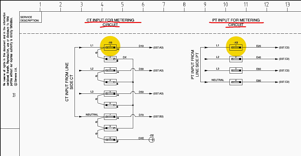
Sheet 036 outlines the dedicated CT and PT inputs for the metering circuits. The metering CTs (which typically have high accuracy classes and saturate early to protect the instruments during short circuits) enter at terminal block X6 (Row A, Columns 5) utilizing the same Elmex KDSL4R shorting link technology.
The metering PT signals enter at terminal block X8 (Row A, Columns 10-11).
Figure 18 – CT Shorting and PT Arrangement For Metering (Sheet 036)
16.2 Mega-Watt Transducer (MW-TDR):
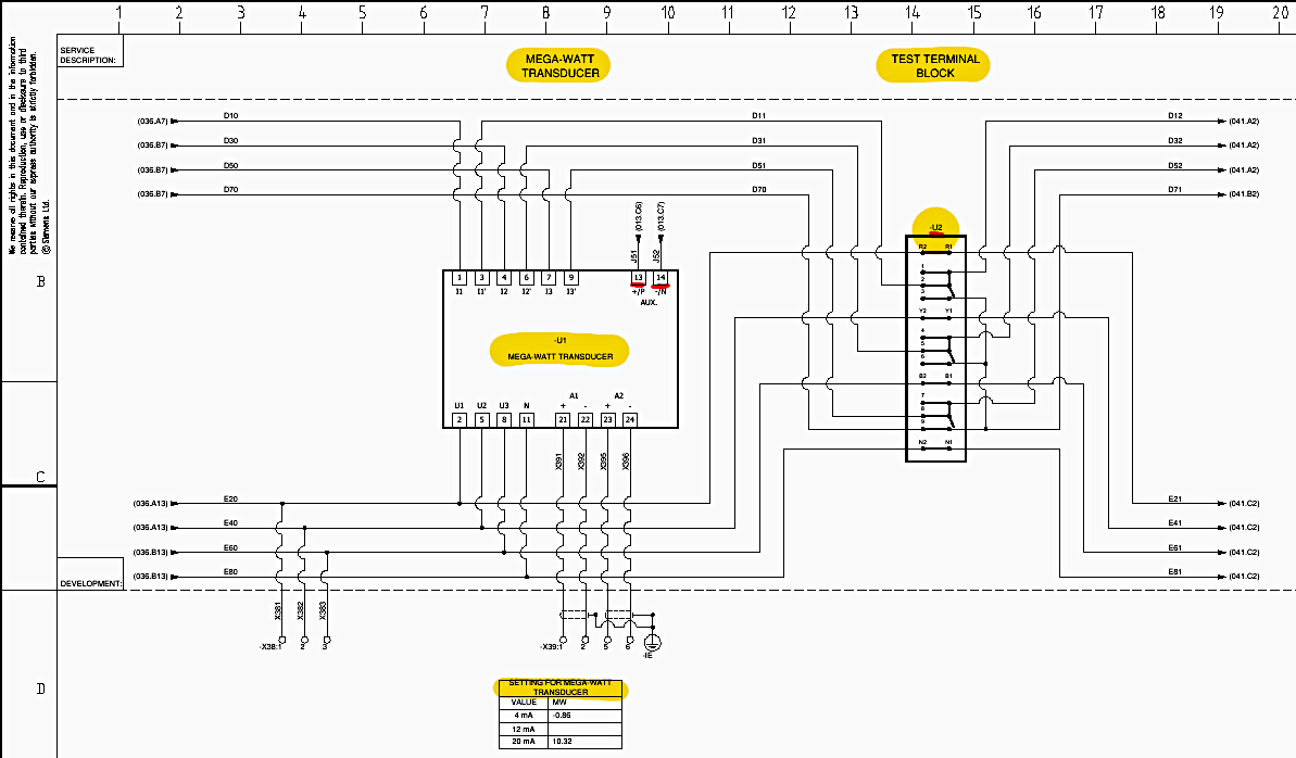
As illustrated on Sheet 037, the analog current and voltage signals are routed into a Secure PT3-623-12F Multi-Function Transducer (U1). This device requires an auxiliary 110 V DC power supply at terminals 13 and 14 (Sheet 037, Row B, Columns 8-10).
It calculates the instantaneous active power generated by the turbine and converts it into a standardized 4-20 mA analog output signal. As per the configuration table (Sheet 037, Row D, Columns 7-9), a 4 mA signal equates to -0.86 MW (reverse power), while a 20 mA signal equates to 10.32 MW.
A Test Terminal Block (U2) is interposed in the CT/PT wiring to allow engineers to inject test signals or bypass the U1 transducer without disrupting the primary wiring during calibration (Sheet 037, Row B, Columns 13-15).
16.3 Power Quality Meter (PQM):
Sheet 041 details the integration of the Satec PM135EH Power Quality Meter (P2). Operating with an accuracy class of 0.2S, this device provides high-resolution data logging of harmonics, voltage sags, and system transients.
The current signals (E21, E41, E61, E81) are routed to the CT terminals on the meter, while the voltages are applied to the V1, V2, V3, and VN terminals.
The PQM features a 2-wire RS-485 port, utilizing shielded twisted pair wiring connected through terminal block X40 (terminals 1, 2, and 3 for the shield) to transmit digital power metrics directly to the overarching plant SCADA system via the Modbus protocol (Sheet 041, Row B, Columns 11-13).
Figure 19 – MW-Transducer & Test Terminal Block Circuit
17. Terminal Arrangements and External Interfacing Architecture
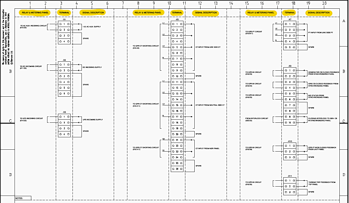
The comprehensive interconnection between the Relay and Metering Panel and the wider power plant infrastructure is achieved through specialized terminal blocks, detailed exhaustively from Sheet 047 to Sheet 052. These blocks utilize Wago spring-loaded mechanisms for secure, vibration-resistant wire retention.
17.1 Sheet 047 (Terminal Arrangement-1)
Details terminal blocks X1 through X11. X1 and X2 manage incoming AC and DC power. X5 and X7 serve as the primary gateways for the protection CT and PT signals. X9 interfaces directly with the Synchronizing Panel, transmitting the Generator CB and Grid CB closed feedback signals, while receiving the Closing Interlock permission.
X11 receives the Turbine Trip feedback from the Turbine Supervisory Panel (TSP).
17.2 Sheet 048 (Terminal Arrangement-2)
Outlines X12 through X20. X12 interfaces with the AVR Panel, exchanging trip feedback and executing the AVR trip command. X13 provides extensive dry contact signaling to the DCS, including GPR Failure, 86A/86B Trip, and DC/UPS supply failures. X17 handles the execution of high-current trip commands to the primary switchgear coils.
X18 provides terminal access for all 15 Binary Inputs of the GPR.
17.3 Sheet 049 (Terminal Arrangement-3)
Details X21A and X21B, dedicated exclusively to the highly sensitive Rotor Earth Fault injection and measurement signals (+ve and Earth) utilizing 4 mm2 wiring. X22 handles the GCB Trip Coil Healthy feedback from the switchgear.
17.4 Sheet 050 (Terminal Arrangement-4)
Focuses on X37, which acts as the massive termination point for the 32-window Minilec Annunciator. Terminals are reserved for W1 through W32, including numerous spare windows for future plant expansion.
17.5 Sheet 051 (Terminal Arrangement-5)
Details X31, providing the complex inter-tripping routing required by the 50BF Breaker Failure logic, sending direct trip commands to local and upstream breakers.
17.6 Sheet 052 (Terminal Arrangement-6)
Covers the metering interconnections. X6 and X8 manage the high-accuracy metering CT and PT signals. X38 outputs the PT voltage reference signals to the Synchronizing Panel for phase matching. X39 routes the scaled 4-20 mA analog active power signals from the MW Transducer to the governor and DCS.
Finally, X40 provides the physical connection interface for the RS-485 Modbus communication network originating from the Power Quality Meter.
Figure 20 – Sheet 047 (Terminal Arrangement-1)
18. Bill of Materials (BOM) Sub-Component Specifications
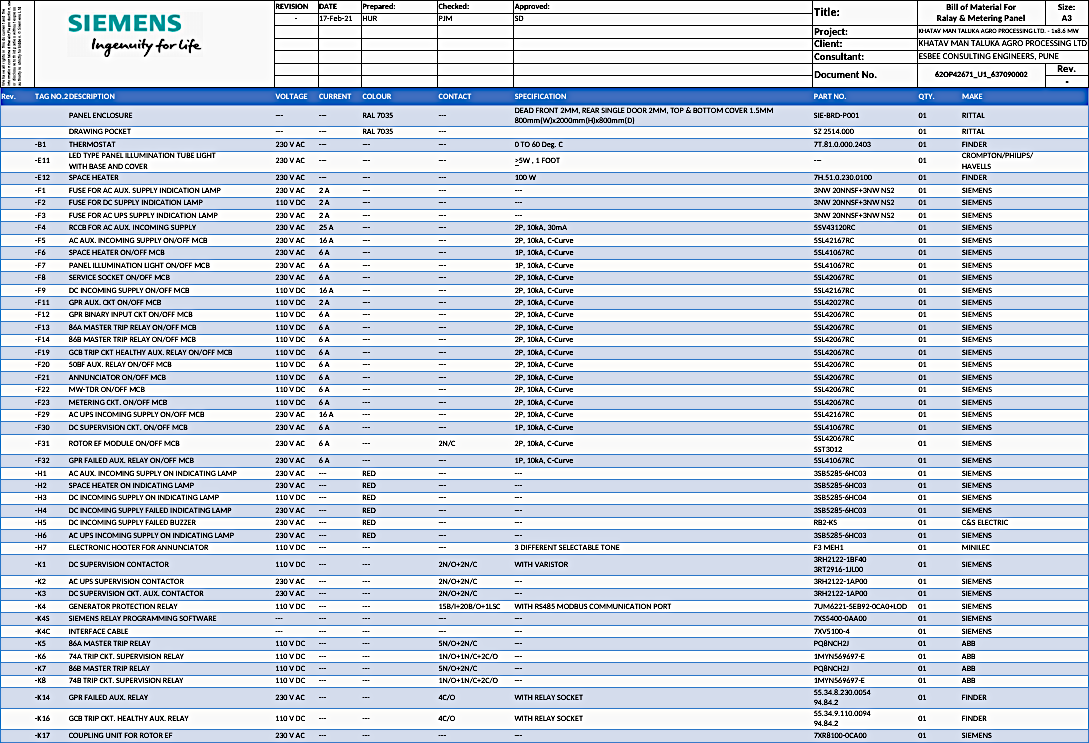
The physical realization of the schematic demands specific engineering components selected for their reliability in high-voltage substation environments. The Bill of Materials (Sheets 056-057) lists the exact OEM parts utilized.
18.2 Enclosures and Infrastructure
The panel structure is a Rittal SIE-BRD-P001 painted in RAL 7035 (light grey), utilizing 2 mm thick sheet steel for the dead front and rear single doors, and 3 mm for the component mounting plates.
18.2 Protection Relays
The core GPR is the Siemens 7UM6221-5EB92-0CA0-L0D, a comprehensive numerical machine protection relay. The relay configuration is executed via DIGSI software (7XS5400-0AA00) utilizing a dedicated interface cable (7XV5100-4). The Rotor E/F Coupling Unit is the Siemens 7XR8100-0CA00.
18.3 Electromechanical Relays
The master tripping duties are handled by ABB PQA-type high-speed lockout relays (P08NCH21), offering a 5N/O + 2N/C configuration for K5 and K7. Trip circuit supervision relies on ABB 1MYN569697-E units (K6, K8). The 50BF multiplication is achieved via an ABB 7N/O relay.
The GPR Fail and Trip Healthy auxiliary relays (K14, K16) are Finder 55.34 series devices utilizing 94.84.2 base sockets with 4 changeover contacts.
18.4 Circuit Protection
Primary circuit isolation relies on Siemens 5SL4 series miniature circuit breakers. For example, the DC incoming MCB is a 5SL42167RC (16 A, C-Curve, 10 kA breaking capacity). The AC auxiliary relies on a Siemens 5SV43120RC 25 A, 30 mA RCCB.
18.5 Terminal Architecture
General field wiring is terminated utilizing WAGO 281-series spring-loaded terminal blocks (e.g., 281-901 for Grey 4 mm2, 281-903/905 for Red/Black AC/DC distribution). Current and potential transformer wiring mandates the use of Elmex KLTDM4 blocks equipped with SCUN end clamps and KDSL4R ring-type shorting links, ensuring total safety during relay current injection testing.
18.6 Operator Interface Devices
The annunciation is provided by a Minilec MBAS 0600 unit with 32 windows. The pushbuttons for Test, Accept, and Reset functions are Siemens 3SB5 series devices (e.g., 3SB5000-0AC01 for the red ‘Accept’ button). The Emergency Trip utilizes a heavily protected Siemens mushroom-head push button with a protective cap (3SU1900-0DY30-0040).
The metering suite features the Satec PM135EH analyzer and a Secure PT3-623-12F precision transducer.
Figure 21[/highlight1] – Bill of Materials (BOM)
19. Summary
The schematics described in this study delineates a highly redundant and meticulously engineered Relay and Metering Panel designed to ensure the operational integrity of an 8.6 MW power generation system.
At the core of this protection scheme is the Siemens 7UM622 numerical Generator Protection Relay (GPR). This relay evaluates high-fidelity analog inputs from line-side and neutral-side current and potential transformers to execute complex protection algorithms, including differential (87G), reverse power (32R), rotor earth fault (64R), and under/over voltage (27/59) functions.
Specialized subsystems, such as the 50BF Breaker Failure logic, provide targeted mitigation strategies to clear faults using upstream grid breakers if the primary generator circuit breaker fails to open.
Beyond protection, the panel seamlessly integrates with the plant’s distributed control system (DCS) and SCADA networks. This is achieved through a 32-window Minilec Annunciator for localized alarms, a Secure Mega-Watt Transducer for active power monitoring, and a Satec Power Quality Meter transmitting harmonic and transient data via an RS-485 Modbus communication link.
Ultimately, the integration of these protective, supervisory, and metering elements forms a cohesive infrastructure capable of rapidly isolating faults while providing operators with exact, real-time telemetry and system diagnostics.
20. Attachment (PDF): Digital Power System Protection Guide For Final Year Undergraduate and Postgraduate Students
Download: Digital Power System Protection Guide For Final Year Undergraduate and Postgraduate Students (for premium members only):
Related electrical guides & articles





Edvard Csanyi
Hi, I'm an electrical engineer, programmer and founder of EEP - Electrical Engineering Portal. I worked twelve years at Schneider Electric in the position of technical support for low- and medium-voltage projects and the design of busbar trunking systems.I'm highly specialized in the design of LV/MV switchgear and low-voltage, high-power busbar trunking (<6300A) in substations, commercial buildings and industry facilities. I'm also a professional in AutoCAD programming.
Profile: Edvard Csanyi