
Proper relay selection
Selection of proper relay is one of the most important stages to have a reliable network. In this article, selection of relay for incoming and outgoing feeders for LV switchgear (motor control centers) and MV switchgear up to 33kV has been discussed.
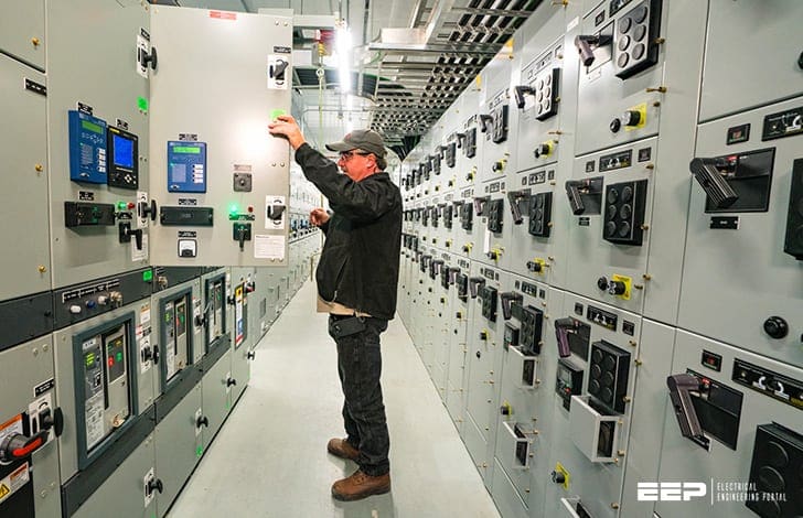 Selection of relay for incoming and outgoing feeders for LV and MV switchgear (up to 33kV) - photo credit: Volta US
The relay selected for this project is illustrated by figures in this article and overall views of single line diagram are shown below. Note that described incomers and feeders per LV switchgear are shown in shown in different colours.
- Low voltage switchgear
- Medium voltage switchgear (POWER CENTER 11-01-MS-01)
1. Low voltage switchgear
1.1 Downstream switchgear of power distribution transformers
(POWER CENTER 11-01-PC-01)
A) Incoming feeder
The minimum protections for incoming feeders of these switchgear are as follows:
- Instantaneous overcurrent (ANSI CODE-50)
- Time overcurrent (ANSI CODE-51)
- Time earth fault (ANSI CODE-51N)
The tripping commands of Buchholz relay and oil temperature of power transformer shall be applied to opening mechanism of incoming circuit breaker. The rated current of current transformers shall be sized in according to the rated current of power transformer.
The under-voltage (27) and restricted earth fault protections (REF-64) shall be considered (if these functions were mentioned in design criteria of project).
In figure 1, the relays selected for LV panels and transformers are presented:
B) Outgoing feeders
For protection of outgoing feeders, the instantaneous overcurrent protection (50) should generally be considered. The nominal current of protection device (molded case circuit breaker or HRC fuse) shall be coordinated according to technical specification of outgoing cable.
If the outgoing feeders should feed the panels and they are installed in hazardous or fire risk area the explosion proof panels must be used.
In addition to the above mentioned protection, the time earth fault protection (51N) with sensitivity of 300 mA needs to be added as well.
1.2 Motor control center (MCC) switchgear
(MCC 11-01-MC-01 and MCC 11-01-MC-02)
A) Incoming feeders:
If the nominal current of feeder is equal or greater than 630A, the necessary protections of incoming circuit breaker should be instantaneous and time overcurrent (ANSI-50, 51).
For protection of control transformer, the required protections shall be GL type with fuses in primary side and MCCB switches in secondary side of control transformer.
It should be noted that, most of the control circuits are generally isolated from the earth and in order to prevent double earth fault, the installation of insulation monitoring relay with alarm signal are recommended in secondary side of control transformers.
B) Motor type feeders:
Minimum protections of feeders which feed directly the electrical motors are as follows:
Short circuit or instantaneous overcurrent protection (50) which can be provided by HRC (High Rupture Capacity) fuses or by magnetic releases of molded case circuit breakers (MCCB).
Overcurrent protection could be provided by thermal overload relay (bi-metal) or with thermal release of the motor protection circuit breaker (MPCB).
There are different ways/methods for protection against phase failure as follows:
- The first one is to use sensitive phase sequence voltage relay
- The second method is to use new thermal overload relays (bimetals) with phase failure function (this method is considered very cost effective and reasonable economically)
- The third method is to use HRC fuse type feeders with fuse-failure contacts against short circuits. Fuse failure contact in control circuits is applied in order to open the power circuits
- Finally, installing miniature circuit breaker with a rating of lower than the rating of power fuses in parallel with fuses is recommended.
In the last case above, three phases MCB shall have auxiliary contacts in order to apply in control circuit for opening the main contactor of motor starter.
When one of the power fuses is failed, a large current will pass through one phase of parallel MCB’s and since the rating of MCB is much lower than the nominal current of power circuit, the MCB will consequently trip and its auxiliary contact will open the power circuit of motor starter.
NOTE! Meanwhile, it should be noted that the short circuit capacity of selected MCB must be coordinated with the short circuit current of the network at the point of installation of MCB.
Nowadays, using of MPCB (motor protection circuit breaker) which has integrated functions of the overload, short circuit and phase fault protection is common.
Thermal protection of stator windings and bearings temperature of motors with rated output power of 100 kW should be anticipated if the above mentioned protections are predicted in the basic design documents or in client standards.
The method of detection and indication of over temperature of motor windings and bearings here is based on RTD sensors. The protection relay should have sufficient input channels for all windings and bearings RTD’s as well as having sufficient protection of motor windings with small output power.
The faulty contacts of PTC or RTD type relays should de-energize the control circuit of motor starter in main contactor coil. In the figure 2 protections of LV motors is shown.
2. Medium voltage switchgear
(POWER CENTER 11-01-MS-01)
2.1 Distribution feeders
The following protections are generally considered for medium voltage outgoing feeders which feed the downstream medium voltage switchgear:
- Instantaneous overcurrent (ANSI CODE-50)
- Time overcurrent (ANSI CODE-51)
- Time earth fault (ANSI CODE-51N)
In some certain conditions, for better reliability and continuation of electric power source, the outgoing feeders should be operated in parallel configuration and for the same purpose, it is necessary to install directional overcurrent protection in addition to the above mentioned protections.
Meanwhile, for incoming feeders of medium voltage distribution switchgear, the undervoltage protection (27) should be predicted in order to apply trip command to outgoing feeders.
In addition, as shown in Figure 3, the trip circuit supervision, Relay 74, must be provided to assure continuity of circuit.
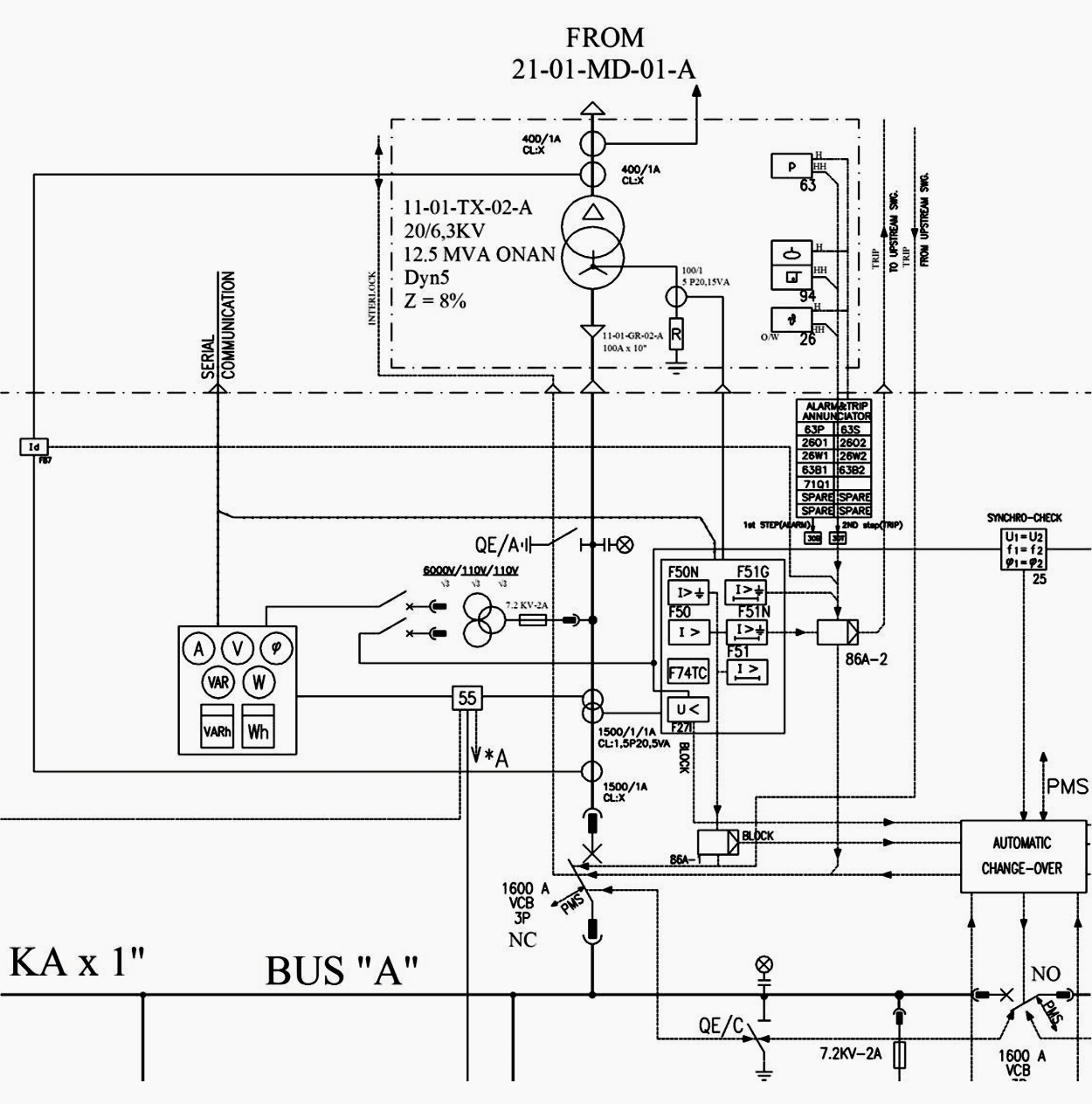
2.2 Transformer feeders
The following protections should be foreseen for the above mentioned feeders:
- Protection of primary windings of transformer against short circuit fault with instantaneous overcurrent relay (ANSI-50) or medium voltage fuses for all outgoing transformer feeder.
- Protection of primary windings of transformer against overcurrent fault with time overcurrent relay (ANSI-51) and time earth fault relay (ANSI-51N) for power distribution transformers with output rating of greater than 630kVA.
- Protection of transformer windings against overtemperature by using oil type thermometer for power transformers with a rating greater than 400kVA.
- Protection of transformer windings against internal fault (electric arc between windings and winding with core or body of transformer) by Buchholz relay for power transformer with rating equal or greater than 400kVA.
- Restricted earth fault protections (ANSI-64) for transformers with ratings from 2500kVA up to 8000kVA must be considered.
- Differential protection (ANSI-87) for power transformers with ratings equal or greater than 10000kVA must be provided as well.
- Internal overpressure protection is needed for transformers without oil expansion tank or power transformers with output rating equal to or greater than 10000kVA.
- Tap changer protections is necessary for transformers which are equipped with on-load voltage regulator (OLTC) in according to vendor recommendations.
Please see Figure 4 for some relays selected for this project.
2.3 Medium voltage motor protections:
Protections of induction motors (squirrel cage or wound rotor), which are generally used in energy industry are as follows:
- Over temperature protection of windings and bearings of motors by RTD sensors and temperature monitor relay for motors with an output power equal or greater than 250 kW.
It should be noted that installation of this protection for motors with an output power between 150 kW up to 250 kW is optional based on each project requirements.
- Protection against short circuit faults by installation of instantaneous overcurrent relay for all motors.
- Protection against overload faults by relay 49 (thermal relay) with facilities to limit number of starts in a period of time in order to reduce the cumulative heat effects on motor windings.The modern microprocessor multi function relays, usually has all necessary functions for motor protections and the function 49 which is the most important protection of the motors, hence the instantaneous overcurrent protection (51) would not be essential for motor protection.
- Protection of motors against rotor temperature rise which is caused by negative sequence current with circulating speed of two times nominal frequency (with respect to rotor). Eddy currents heat should be protected by 46 relay (reverse phase or phase balance).
- In “wound rotor type motors”, if any fault happens in rotor systems, (i.e., circulation of electrolyte or any other problem in rotor contacts with windings), according to motor manufacturer’s specific design, the motor start up command will be blocked and the relay with function (51LR) shall be used to protect motor.In case of any rotor failure during normal running, this relay must trip the motor feeder as well.
- Protection against earth fault (51N) by using core balance CT or digital relays that sum up secondary currents of CTs on each phase.
- Protection against bearings vibration for motors with rated power greater than 1500 kW shall be provided with vibration monitoring relay.
- It is advisable to use lock out relay for medium voltage transformer and motor type feeders in order to block the closing command of breaker before fault removal.
Reference // Design of Electrical Power Supply System in an Oil and Gas refinery by Reza Vafamehr (Department of Energy and Environment; Division of Electric Power Engineering at CHALMERS UNIVERSITY OF TECHNOLOGY


Kindly find the requirements and technical specifications of 11kv transformer incomer panels that we want you to give us a quotation.
Regards
ACKIM
Which software did you use to produce the single line drawing?
I need good knowledge on FACTS, REACTIVE POWER CONTROL ,POWER SYSTEM QUALITY .
Hi Edvard, I was wondering if there is a method to achieve sensitive earth protection for a 22kV 3ph feeder in which we do not have to use a sensitive earth CT.
Thanks
I am teaching for under graduate students. Switchgear and protection. This article helps me.
very interesting analyse but a little bit “old fashion”; All the protection feature syou describe are correct but as the tendancy is to try to solve and localise the fault in a much more precise way, the basic OC or Dir OC do not match this objective; The solution is more today as also we have more and more potential distributed generation and need to avoid any black-out of using differential cable protection (87L) for short and medium MV cables;, 87T with extended feature for transformers an d87B for the MV/MV busbar or HV/MV busbar. This with fast CB allows to ensure a switching/isolating time of les than 100 ms compar eto the “traditional ” way where the typical time (including Sw) is more around 300 to 500 ms. A key point is also the choise of the architecture and the correct choice in the MV and LV switching elements.
Information Provided is really great, share as much as electrical technical information.
Hello Ed,
I am a retired Electrical Engineer but relays have always fascinated me. My days we had electro mechnaical ones and now a days we have fully digital ones. i would appreciate if you can share some free info on these new relay series, their usage and design and some practical tips in designing to use them and test them using simulation like ETAP.
Regards
Mohammed
Splendid articles. Thank you. However one small request – since i am a technical trainer for a facility management company, i would like some more basic articles regarding relays, breakers, harmonics, UPS etc if possible
Thanking you.
Sincerely yours
Shambu Kumar
Why can’t DC be used in large electrical devices ??