
Estimated Study Time: 14 minutes
Protective Relaying Schemes
A substation can employ many relaying systems to protect the equipment associated with the station. The most important of these are: transmission and distribution lines emanating from the station, step-up and step-down transformers, station buses, breakers, shunt and series reactors and shunt and series capacitors.
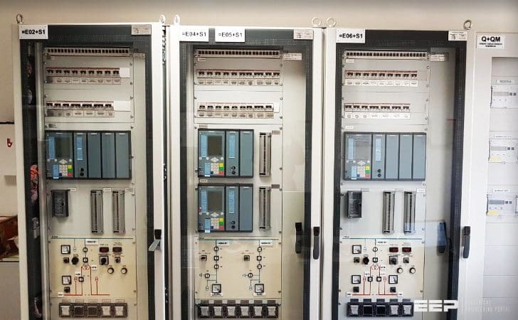 Six different types of relaying schemes to protect the EHV and UHV substation equipment
Substations serving bulk transmission system circuits must provide a high order of reliability and security in order to provide continuity of service to the system. More and more emphasis is being placed on very sophisticated relaying systems which must function reliably and at high speeds to clear line and station faults while minimizing false tripping.
Most EHV and UHV systems now use two sets of protective relays for lines, buses, and transformers.
Many utilities still use one set of electromechanical relays for transmission-line protection, with a completely separate, redundant set of solid-state relays to provide a second protective relaying package or two completely separate redundant sets of solid-state relays.
For more difficult relaying applications, such as EHV lines using series capacitors in the line, some companies always use two sets of solid-state relays to provide the protection systems.
Transmission-line relay terminals are located at the substation and employ many different types of relaying schemes that include the following:
1. Pilot-Wire Relaying
Pilot-wire relaying is an adaptation of the principle of differential relaying to line protection and functions to provide high-speed clearing of the line for faults anywhere on the line.
Pilots include wire pilot (using a two-wire pair between the ends of the line), carrier-current pilots, microwave pilots, fiber-optics pilots, and the use of audio-tone equipment over wire, carrier, fiber-optics, or microwave.
The transmission lines may have two or more terminals each with circuit breakers for disconnecting the line from the rest of the power system. All the relaying systems described can be used on two-terminal or multiterminal lines. The relaying systems program the automatic operation of the circuit breakers during power-system faults.
Three different types of such a channel are presently in use, and they are called “wire pilot,” “carrier-current pilot,” and “microwave pilot.”
A wire pilot consists generally of a two-wire circuit of the telephone-line type, either open wire or cable. Frequently, such circuits are rented from the local telephone company.
A carrier-current pilot for protective-relaying purposes is one in which low-voltage, high-frequency (30 kc to 200 kc) currents are transmitted along a conductor of a power line to a receiver at the other end, the earth and ground wire generally acting as the return conductor.
A microwave pilot is an ultra-high frequency radio system operating above 900 megacycles. A wire pilot is generally economical for distances up to 5 or 10 miles, beyond which a carrier-current pilot usually becomes more economical.
Microwave pilots are used when the number of services requiring pilot channels exceeds the technical or economic capabilities of carrier current.
Purpose of a pilot
Figure 1 is a one-line diagram of a transmission-line section connecting stations A and B, and showing a portion of an adjoining line section beyond B. Assume that you were at station A, where very accurate meters were available for reading voltage, current, and the phase angle between them for the line section AB.
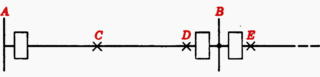
Knowing the impedance characteristics per unit length of the line, and the distance from A to B, you could, like a distance relay, tell the difference between a short circuit at C in the middle of the line and at D, the far end of the line.
But you could not possibly distinguish between a fault at D and a fault at E just beyond the breaker of the adjoining line section, because the impedance between D and E would be so small as to produce a negligible difference in the quantities that you were measuring.
Even though you might detect a slight difference, you could not be sure how much of it was owing to inaccuracies, though slight, in your meters or in the current and voltage transformers supplying your meters.
And certainly, you would have difficulties if offset current waves were involved.
There would be practically a complete reversal in the currents, or, in other words, approximately a 180° phase-angle difference.
What is needed at station A, therefore, is some sort of indication when the phase angle of the current at station B (with respect to the current at A) is different by approximately 180° from its value for faults in the line section A B. The same need exists at station B for faults on either side of station A.
This information can be provided either by providing each station with an appropriate sample of the actual currents at the other station, or by a signal from the other station when its current phase angle is approximately 180° different from that for a fault in the line section being protected.
2. Direct Underreaching Fault Relays
These relays (Figure 2) at each terminal of the protected line sense fault power flow into the line. Their zones of operation must overlap but not overreach any remote terminals.
The operation of the relays at any terminal initiates both the opening of the local breaker and the transmission of a continuous remote tripping signal to effect instantaneous operation of all remote breakers.
For example, in Figure 2 below, for a line fault near bus A, the fault relays at A open (trip) breaker A directly and send a transfer trip signal to B. The reception of this trip signal at B trips breaker B.
3. Permissive Underreaching Relays
The operation and equipment for this system are the same as those of the direct underreaching system, with the addition of fault-detector units at each terminal.
The fault detectors must overreach all remote terminals. They are used to provide added security by supervising remote tripping. Thus, the fault relays operate as shown in Figure 2 and the fault detectors as shown in Figure 3.
As an example, for a fault near A in Figure 2, the fault relays at A trip breaker A directly and send a transfer trip signal to B. The reception of the trip signal plus the operation of the fault detector relays at B (Figure 3) trip breaker B.

relaying system
4. Permissive Overreaching Relays
Fault relays at each terminal of the protected line sense fault power flow into the line, with their zones of operation overreaching all remote terminals.
Similarly, the relays at B operate and transmit a trip signal to A. Breaker A is tripped by the operation of the fault relay A plus the remote trip signal from B.
Likewise, breaker B is tripped by the operation of fault relay B plus the remote trip signal from A.
5. Directional-Comparison Relays
The channel signal in these systems (Figure 4) is used to block tripping in contrast to its use to initiate tripping in the preceding three systems. Fault relays at each terminal of the protected line section sense fault power flow into the line.
For example, in Figure 3 the blocking zone at B must extend further behind breaker B (to the right) than the operating zone of the fault relays at A.
Correspondingly, the blocking zone at A must extend further out into the system (to the left) than the operating zone of the fault relays at B.

For an internal fault on line AB, no channel signal is transmitted (or if transmitted, it is cut off by the fault relays) from any terminal. In this absence of any channel signal, fault relays at A instantly trip breaker A, and fault relays at B instantly trip breaker B.
For the external fault to the right of B as shown in Figure 3, the blocking zone relays at B transmit a blocking channel signal to prevent the fault relays at A from tripping breaker A.
Breaker B is not tripped because the B operating zone does not see this fault.
6. Phase-Comparison Relays
The three line currents at each end of the protected line are converted into a proportional single-phase voltage. The phase angles of the voltages are compared by permitting the positive half-cycle of the voltage to transmit a half-wave signal block over the pilot channel.
For external faults, these blocks are out of phase so that alternately the local and then the remote signal provide essentially a continuous signal to block or prevent tripping. For internal faults, the local and remote signals are essentially in phase so that approximately a half-cycle of no channel signal exists.
This is used to permit the fault relays at each terminal to trip their respective breakers.
References //
- Standard handbook for el. engineers – Substations by W. Bruce Dietzman and Philip C. Bolin
- Wire-Pilot Relays by GE GRID
Related electrical guides & articles


Edvard Csanyi
Hi, I'm an electrical engineer, programmer and founder of EEP - Electrical Engineering Portal. I worked twelve years at Schneider Electric in the position of technical support for low- and medium-voltage projects and the design of busbar trunking systems.I'm highly specialized in the design of LV/MV switchgear and low-voltage, high-power busbar trunking (<6300A) in substations, commercial buildings and industry facilities. I'm also a professional in AutoCAD programming.
Profile: Edvard Csanyi

Real Integrated Systems Engineering, the dynamic systems presentations are beyond comment just keep moving for current and next-generation Engineers benefits nationwide.
very clear and concisely explained. thank you
Really wonderful tutorials. Vast spectrum of technology being dealt … absolutely great.
Dear Sir… Good Evening…
Sir please send me vaccum contactor (thyristor contactor/ G1 Contactor) … any PDF Or link..
super