SCADA, DMS and RTU
This technical article deals with the devices that make possible the interface with the primary process (e.g. cables and switchgear) in a secondary substation from a central point, like central control databases/systems that facilitate all kinds of stakeholders with data.
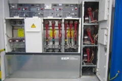
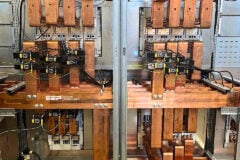
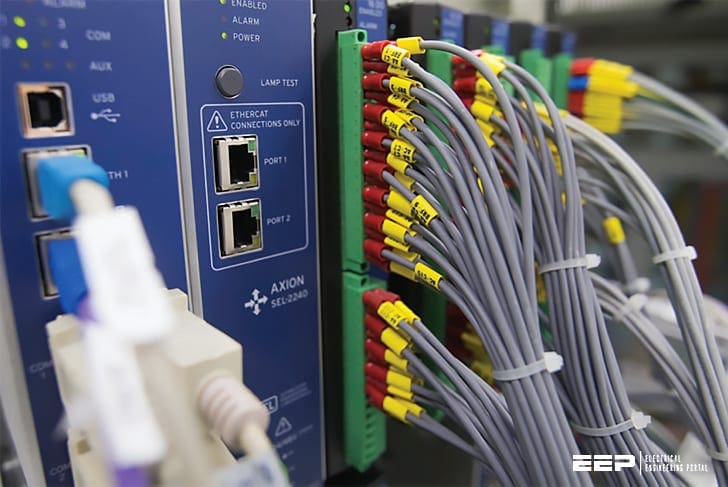
To enable this functionality, there has to be a chain of devices starting with the sensor in or on the primary infrastructure and ending on the screen of a stakeholder.
This article will use a top-down approach with a brief description of SCADA/DMS systems because they are currently the most common central systems. Then, an overview of the most common data communication technologies is presented.
Finally, the heart of this system is described: the Remote Terminal Unit (RTU).
RTU is the intermediary between the primary process and the central system to connect all the data and make logical operations with the data.


- SCADA and DMS
- Communication to Secondary Substations
- Remote Terminal Unit (RTU)
- Measuring, Monitoring and Control
- UPS
- Main applications
1. SCADA and DMS
Traditionally, if secondary substations are equipped with any form of automation, they send data to a Supervisory Control and Data Acquisition (SCADA) system. This SCADA system makes it possible for controllers to watch over the grid 24/7.
A SCADA system uses a Real Time Database for real time operation. Of course, relevant data are shared with off line databases, allowing back office analysis.
The system monitors certain conditions, so as to determine if an alarm event has occurred (alarm handling functions) and, possibly, to perform consequently proper actions (e.g., activation of automatic procedures).
SCADA system’s databases and software programs offer a human machine interface (HMI) to provide schematics, trending, diagnostic data and so on.


Where many SCADA systems are quite straightforward, Distribution Management Systems (DMS) can provide the controllers (and other stakeholders) real-time and offline calculations such as state estimation, power flow, optimal switching etc.
A DMS system is fed by SCADA and corporate archives with dynamic data such as status of switches/breakers, measurement etc. and more, “static data” such as network size, load and generation profiles, characteristic of conductors etc.
The different SCADA and DMS solutions adopted have direct impact on:
- Naming convention
- Network representation (diagrams, schemes, …)
- Devices configuration (directly by the SCADA and/or by means of concentrators and/or converters/data gateways)
- Network management
- Network operation, both in case of manual and remote controlled operations
- Update of the connection state of the network
- Automation functionalities, both at grid and substation level.
2. Communication to Secondary Substations
External communication is intended as the link between the substation and other systems. This can be communication between substations to a SCADA/DMS system or to a remote management tool.
Different types of data communication technologies will be described:
- xDSL
- FO (Fiber Optic) Glass fiber
- PowerLine Carrier or Broadband over PowerLine
- Dial-up
- WiMax
- GPRS/UMTS/LTE
2.1 xDSL
Digital subscriber line (DSL) has a relative high-speed technology based on two-wire twisted pair lines like existing telephone cables.
Distribution system operators can use this technology from third party suppliers or can use the technology on their own old existing networks. This can be an interesting solution for areas with no wireless communication or when there is an existing network available.
2.2 FO (Fiber Optic) Glass fiber
Glass fiber is based on optical signals. Therefore, it’s ideal for high speed and long distance and with lowest latency of all communication systems.
This way of communication is not so common for secondary substations because it’s quite costly to install them, if not done while installing power cables.
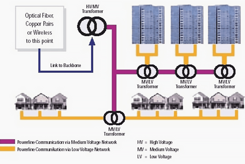

2.3 PLC/BPL
PowerLine Carrier (PLC) or Broadband over PowerLine (BPL) uses the energy grid for communication.
Usually, the data from the secondary substation are communicated over the MV network to a primary substation from where they are communicated through a different technology.


2.4 Dial-up
Older serial connections use dial-up modems. These can be wired or wireless. In most wireless cases, the dial-up connection is triggered by events. Dial-up connections should be included in security checks.
2.5 WiMax
In rural areas, WiMax is an alternative to make wireless communication reliable and independent from public communication networks. Speed and latency are similar to Fiber Optic communication.
Applications using WiMax are up-to-date mainly on overhead lines including tower substations.


2.6 GPRS/UMTS/LTE
For countries with a good mobile network, this is often used for the automation of secondary substations. The advantage is that it’s affordable and widely available. The disadvantage is that it’s harder to get secured and the availability depends on the traffic of other users of the network.
Earlier generations are the 3G UMTS technology and the 2G GPRS technology.
3. RTU
The expectations and tasks to be performed by RTU have increased over the years as result of Smart Grid requirements. Traditionally, it secures collection of analog and digital inputs, provision of commands and, on top of that, communication through standard protocol to the SCADA system.
The usual RTU has modular architecture with several cards securing specific functionalities in order to be scalable.
In general, we can see modular or integrated RTUs depending on customers’ requirements in terms of functionalities and needs and also with in-build or external communication.


The main tasks of the Remote Terminal Unit (RTU) are:
- Facilitating efficient and reliable communication between secondary substation and control center
- Collecting and processing information from the secondary substation and communicating the information to SCADA
- Enabling the monitoring and controlling of the secondary substation
The Remote Terminal Unit shall be placed either indoor, inside the secondary substations, or outdoor, depending on the type of the secondary substation itself. Therefore, these operational conditions and the installation features shall be taken into account, for example, the IP protection shall be increased for outdoor installations.
The basic specifications for the RTU system with the limit values for climatic performance are determined by the IEC 61850-3 “G” standard (Ed. 2.0):


3.1 Main RTU Functions
Some important functions are briefly presented in the following Table 1 below.
Table 1 – Main RTU functions
Function | Basic Function | Special Function |
Hardware | Hardware watchdog timer Hardware clock (RTC) Operation without ventilator | |
Time setting | Recife Timestamp with Protocol IEC 60870-5-101(4); SNTP or DCF77 (GPS) Antenna | Send Timestamp on Substation with Protocol IEC60870-5-101(3);(4) or SNTP |
Firewall | Switch On / Off every Ethernet an USB Communication Port with the integral Firewall on Board off the CPU | |
Security | Encryption Telegram with different algorithm via Tunneling or Transport mode between RTU and Control Center or RTU and Substation | Authentication with Pre shared Key or Route Certificate |
DHCP Client or Server | The IP address of the device can be assigned by an external DHCP server, or stored as a fixed setting in the form of static IP address. | Optional, with the DHCP server on Board of the RTU you can dispense with the parameter assignment of the network addresses of the DHCP client. Thus, the clients don’t require a fixed allocation of the IP address. |
Patch- and UpdateManagement | Local Update Firmware CPU and Parameter RTU from the Central Station | Remote automatic Update Firmware CPU and Parameter RTU from the Central Station |
Data Logging | Archive Data (System information an Process data) local on the CPU on SD-Card or internal Flash-Card | Archive Information for IT Security logging Information |
Documentation on Board of the RTU | On Board of the CPU (internal Flash Card) is a User manual that describes the functionality, installation and commissioning of the processing unit for a local network substation. Additionally, the diagnosis functions and service functions are described. | |
Communication between RTU and central processing unit for Grid network systems | The availability and performance of the System (communication services for RTU and Central Unit) are 99.95% for commands and 97% for remaining less priority communication. | The communication for send a command and answer from the RTU to the Central Processing Unit are max. 3 sec. |
3.2 Flexible I/O card and communication interface
In order to meet the needs of today’s energy supplier, a Remote Terminal Unit is required with a modular system platform. This system platform should have an open scalable architecture that is easy to adapt to future requirements without any hardware upgrade.
The RTU should have at least the following physically separate communication interfaces:
- 2 Ethernet Ports RJ45 (Full or half Duplex Communication Ports)
- 2 COM Ports RS232 and / or RS485 (RS422)
This also includes modules for the direct measurement of current and voltage in the medium and low voltage.


3.3 Binary or analogue input or output
The requirements of the binary and analog input or output cards are:
Card | Voltage | Signal | Attribute |
Binary Input | 24-220V DC | single- double; point indication; counter and Tap Change information | Timestamp, Qualifier |
Binary Command | Relay | Single- double Command or Signal Output | Timestamp, Qualifier |
Analog Input | mA; PT100 | Bipolar or unipolar Measurement (scaled, normalized, float) | Timestamp, Qualifier |
Analog Output | mA, V | Bipolar or unipolar Measurement (scaled, normalized, float) | Timestamp, Qualifier |
Direct Measurement | 0… 100V√3 1/5A or 300V 1/5A | UL1; UL2; UL3, IL1; IL2;IL3; P;Q;S UL12; UL23:UL13; IL1; IL2;IL3; P;Q;S and F, Cosφ… | Timestamp, Qualifier |
3.4 Internal communication
The state of the art of the infrastructure into the substation is a communication per Fieldbus RS485 via Modbus or IEC 60870-5-103.
Another possibility might be external router used not only for RTU communication, but also for other devices.
3.5 External communication
The state of the art of the infrastructure from substations to superior systems is a communication per Ethernet or RS232 interfaces using IEC 60870-5-101, IEC 60870-5-104.
In the future, we might see the communication with IEC 61850 more often using it as a communication to control centre and between the secondary substations as a very quick way to share grid status.
3.6 Serial (RS-232, RS-485), Modbus, IEC 101-103
The requirements of the serial communication ports are presented in Table 2.
Table 2 – Requirements of the serial communication ports
Protocol | Port | Baud-Rate | Function |
IEC60870-5-101 | RS232 | 50… 38k4 Bit/s | unbalanced / balanced |
IEC60870-5-103 | RS485 | 9k6 or 19k2 Bit/s | unbalanced |
Modbus RTU | RS485 | 50… 38k2 Bit/s | unbalanced |
3.7 Ethernet (network equipment), IEC 104, IEC 61850
The requirements of the Ethernet communication ports are presented in Table 3 below.
Table 3 – Requirements of the Ethernet communication ports
Protocol | Function | Port | Virtual Connection |
IEC60870-5-104 | Client Server | RJ45 or Fiber full or half Duplex Communication with 10/100 Mbyte/s | 1…N 1 |
Modbus TCP | Client Server | RJ45 full or half Duplex Communication with 10/100 Mbyte/s | 1…N 1 |
Time Setting SNTP | Client Server | RJ45 or Fiber full or half Duplex Communication with 10/100 Mbyte/s | 1…4 1 |
HTTPS | Client | USB or RJ45 for Service and Engineering from Local or Remote | 1…N |
4. Measuring, Monitoring and Control
The essential function of the RTU is used for the monitoring the Distribution Grid – Grid monitoring: Short-circuit and earth fault detection and monitoring of switch status and device condition (e.g., loss of SF6 pressure).


4.1 PLC (logic function)
RTU is the first level of the transformation of a substation into a smart secondary substation. For higher-level automation, signals can be processed inside, using a Programmable Logic Function, which is typically named after former additional processor needs PLC (programmable logical controller).
Algorithms written with the PLC function can be part of automated switching solution or Volt/VAR control applications and make operation therefore independent of superior systems.


Automated switching for Fault Isolation and Service Restoration:
- Derive necessary action to isolate faulty section
- Execute close command on normal open point to restore power
- Reconfigure to normal after fault clearance
Voltage stability:
- Voltage regulator in the distribution substation or in-phase regulator in the field
- Active and reactive power control for decentralized generating plants and loads
- Wide-area control for transformer and in-phase regulator
Load and Flow Control:
- Load flow control based on the overall grid state
5. UPS
All mentioned active devices in this article work on Direct Current (DC) typically 24V, but other voltages are also possible.
In order to keep the communication with the substation and protection in the substation active during outages, there is a need for an uninterruptable power supply (UPS) that keeps the devices active during a period of several hours.


5.1 AC/DC converter
The main task of AC/DC converters is to secure sufficient and reliable power supply to RTUs and other devices installed in secondary substations.
The power output should reflect expected consumptions of all devices; in certain applications, the redundant configuration might be needed.


Below mentioned list represents the usual set of functionalities to be considered by the project designer:
- Requested current and voltage output
- Possible UPS integration (extra connection)
- Power supply and battery management
- Communication capabilities (protocol and interface)
- Protection (overvoltage, overcurrent)
- Operation conditions (temperature, humidity, …)
- Temperature management – heating/cooling
5.2 Battery, Lead-acid, Powercap
The conventional battery system requirements are:
- Capacity fulfilling requested needs (e.g., 4/8 hours of supply of operation including 10 switching operations at reference conditions)
- Size
- Operation conditions (low temperature is crucial)
- Maintenance requirements (e.g., maintenance free, ease of replacement)
- Type of battery – Pb, Li-IOn, LiPo (regular backup) or super capacitor covering rather shorter outages but with lower price and faster charging / discharging
- Expected lifetime and its degradation (e.g., 10 years of capacity not lower than 80%)


6. Main applications
6.1 Network operation: remote control and supervision
- Asset supervision
- Remote controls of the MV switchgears (circuit-breakers, disconnectors)
- Measurements
- Monitoring and presenting the information on the state of the switches (breakers, disconnectors)
- Alarm processing, display and dispatching to control center
- Earth fault and short circuit indications (indications must work both in isolated and compensated network and also in intermittent fault conditions)
6.2 Asset management
- Measurements: current, voltage, temperature, e.g., transformer
- Based on the need of the utility current and voltage measurements on LV, MV or both LV and MV
- Security: SF6 pressure alarm, temperature alarms, door alarm, fire alarm …
6.3 Power quality
Power quality measurements according to EN 50160 standard are:
- Variation of the voltage level (10 min averages min, max and average + ranged limits been exceeded)
- Variation of the current level (10 min averages max and average + ranged limits been exceeded)
- Active and reactive power (hourly values)
- Phase voltage and current distortion level THD
Sources:
- Working Group on Smart Secondary Substations – Technology Development and Distribution System Benefits – CIRED (Luca Giansante, Domenico Lamanna, Gianni Andreella, Roberto Calone, Jon Bjarte Carlsen, Yves Chollot, Giovanni Dominici, Wolfgang Friedrich, Iñaki Garabieta, Jarkko Holmlund, Pierluigi Invernizzi, Eduardo Jaureguibeitia, Domenico Lamanna, Jose Antonio Lozano, Flavio Mauri, Juan Carlos Pérez Quesada, Enrico Ragaini, Juan Antonio Sánchez Ruiz, Bernd Schuepferling and Osmo Siirto.
- Uninterruptible Power Supply in Distribution Substations’s Auxiliary Circuits by Hardi Hõimoja at Tallinn University of Technology
Clear insight and key information noted.
Very good article giving valuable insights
MUY BUEN DESARROLLO TECNICOS
Great Job
Nice Job. Thanx
Are you offering certificate after studying
Good points