
Estimated Study Time: 4 minutes
Electrically safe area //
There are certain situations where it is desirable for a room to be totally isolated from the Protective Earth conductor (e.g. for conducting special tests in a laboratory etc.). These rooms are regarded as an electrically safe area and the walls and floor should be made of non-conductive materials.
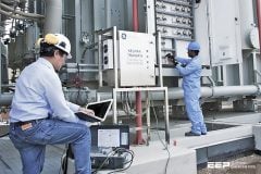
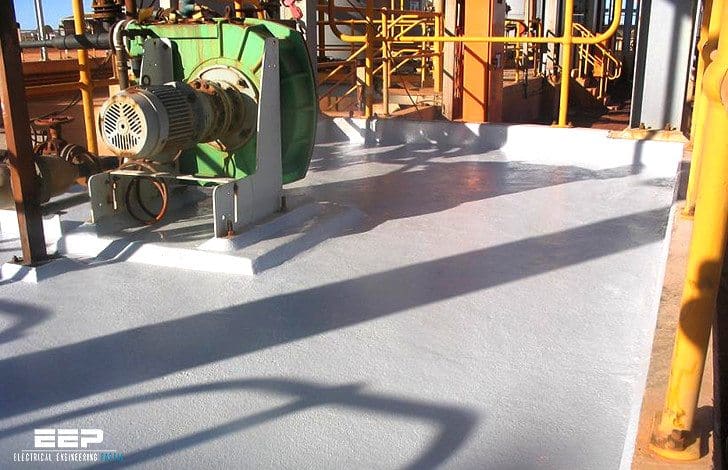 Resistance measurement of non-conductive walls and floors (photo credit: geckospecialcoatings.com.au)
The arrangement of any electrical equipment in those rooms should be of such a manner that:
- It is not possible for two live conductors , with different potentials , to be touched simultaneously in the case of a basic insulation fault.
- It is not possible for any combination of active and passive accessible conductive parts to be touched simultaneously.
The resistance of non-conductive walls and floors shall be measured with an Insulation Resistance tester using the procedure described below. Special measurement electrodes described below are to be used.
The measurement is to be carried out between the measurement electrode and the protection conductor PE, which is only accessible outside of the tested non-conductive room. To create a better electrical contact, a wet patch (270 mm × 270 mm) shall be placed between the measurement electrode and the surface under test.
The value of test voltage shall be:
- 500 V – where the nominal mains voltage with respect to ground is lower than 500 V
- 1000 V – where the nominal mains voltage with respect to ground is higher than 500 V
The value of the measured and corrected test result must be higher than:
- 50 kW – where the nominal mains voltage with respect to ground is lower than 500V
- 100 kW – where the nominal mains voltage with respect to ground is higher than 500 V
Two important notes //
- It is advisable that the measurement to be carried out using both polarities of test voltage (reversed test terminals) and the average of both results be taken.
- Wait until the test result is stabilized before taking the reading.
Reference // Measurements on electric installations in theory and practice – METREL (Download guide)
Related electrical guides & articles


Edvard Csanyi
Hi, I'm an electrical engineer, programmer and founder of EEP - Electrical Engineering Portal. I worked twelve years at Schneider Electric in the position of technical support for low- and medium-voltage projects and the design of busbar trunking systems.I'm highly specialized in the design of LV/MV switchgear and low-voltage, high-power busbar trunking (<6300A) in substations, commercial buildings and industry facilities. I'm also a professional in AutoCAD programming.
Profile: Edvard Csanyi

Misprint ? I presume that the electrical floor resistance is not in kW but in kohm…
Thanks Edvard !
Very useful for our electrical engineers!