
Estimated Study Time: 21 minutes
RMU wiring schemes and design
In terms of operational requirements, it is pretty evident what a customer expects out of a Ring Main Unit – a hassle-free and uninterrupted distribution of power supply to electrical loads from one or more available sources. The onus is on the designer to meet those expectations in design and fabrication.
 The most popular wiring schemes and design essences of a Ring Main Unit (RMU)
From a design perspective, RMU is a TEE point of power supply aided with extra protection and control, which divides the load current and interrupts any fault or short circuits.
RMU is an epitome of modularity and portability in medium voltage power distribution that makes the Selection of source and power supply to multiple downstream loads look effortless and compact.
We shall discuss the most commonly used configurations for RMU along with its interconnections, cabling, protection, and other important aspects of installations.
- RMU vs switchgear assembly (similar, yet different)
- Essences of RMU
- RMU connection configurations
- Bonus: AutoCAD drawing – RMU schematics
1. RMU vs switchgear assembly; similar, yet different
To simply put it in one sentence, a Ring Main Unit is an extended version of switchgear or has switchgear integrated into it, but vice versa might not hold. However, in comparison to a complete switchgear assembly is admittedly close since a switchgear assembly also houses primary components to control or interrupt the current flow and other ancillary operating, metering, and monitoring components.
The difference, however, lies in the application and portability. The switchgear assemblies are better suited for large power utility substations with numerous outgoing feeders that require dedicated feeder protection. Protection via individual switchgear cubicles of the assembly arguably provides better flexibility in terms of maintenance and operability.
In addition, the modern RMUs are available with an enclosed SF6 insulated chamber that houses all operational switches and breakers, which immensely reduces the size of the module and makes it maintenance-free, elongating its useful life over more than 30 years.
Figure 1 – Ring main power distribution principle in a facility
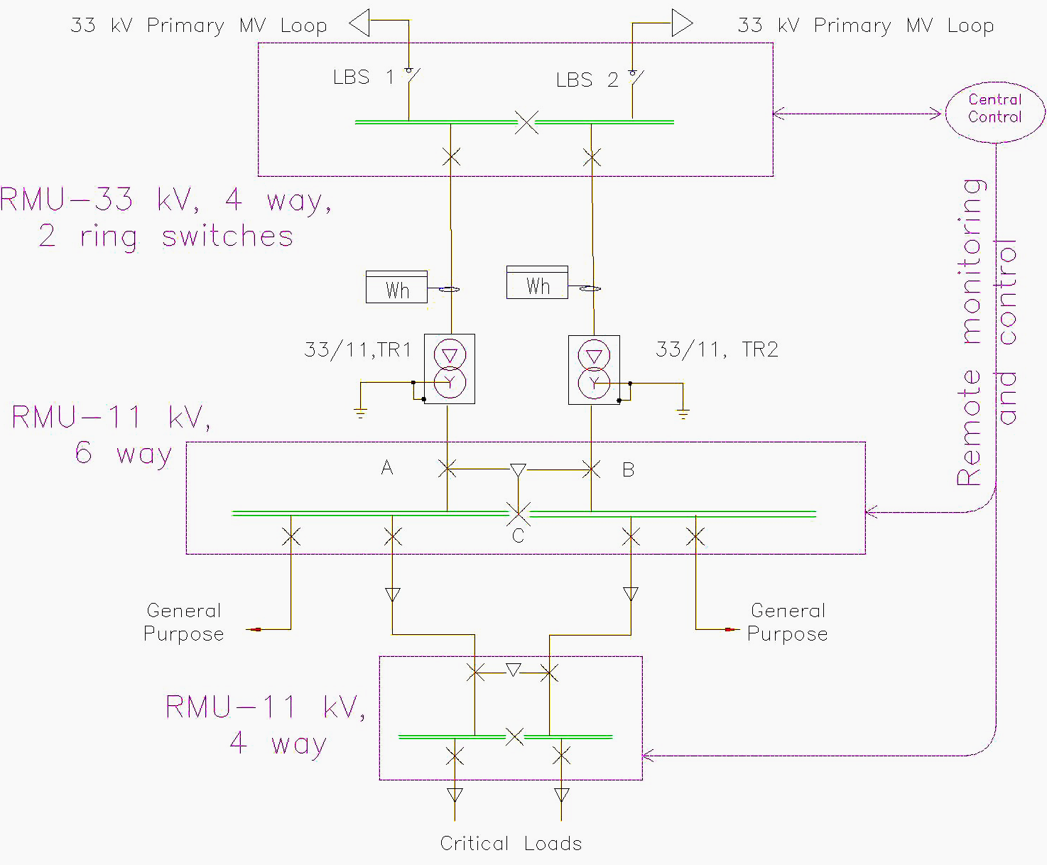
Ring Main Units are an integral part of modern ring main power distribution systems for critical loads. For instance, the above schematic borrows a leaf from a ring main power distribution network of an airport which consists of multilevel rings of medium voltage realized with the help of Ring Main Units.
The primary 33 kV RMU, equipped with two load break switches and two SF6 circuit breakers, is fed with two 33 kV incoming feeders. The outgoing feeders supply two different step-down 33/11 kV power transformers each leading to downstream 11 kV RMUs, which forms multiple 11 kV secondary distribution rings for ancillary bulk loads.
Furthermore, the compact size, modularity, and portability give RMUs a substantial advantage over other options, as they allow much faster installation and commissioning.
Related electrical guides & articles


Bishal Lamichhane
Electrical Engineer (B.E Electrical, M. Sc Engineering) with specialization in energy systems planning. Actively involved in design and supervision of LV/MV substations, power supply augmentations and electrification for utilities and bulk consumers like airports and commercial entities. An enthusiast and scholar of power systems analysis.Profile: Bishal Lamichhane
