
Estimated Study Time: 33 minutes
Harmonic Emissions & Consequences
Modern power systems are undergoing a profound transformation. The rise of harmonic distortion is becoming a huge problem. The traditional grid once dominated by large synchronous generators and linear loads—has evolved into a complex, inverter-rich network driven by renewable generation, battery energy storage systems (BESS), electric vehicle chargers, power electronics, and cable-heavy connections.
 The Massive Rise of Harmonic Distortion in Power Systems
This transition has brought significant benefits in reliability, sustainability, and flexibility, but it has also introduced new technical challenges, the most critical of which is the rise in harmonic distortion.
The technical artice includes important general principles applicable to the harmonic management of power systems. Nevertheless, unforeseen challenges may arise when efforts are undertaken to implement them in extensive power systems. The standard’s prescribed process for calculating harmonic emission levels restricts the voltage at the connection point.
There may be instances where the peak harmonic voltages are distant from the Point of Common Coupling (PCC). This can be explained by considering the interactions between each injecting load and all other busbars simultaneously.
This results in the establishment of a harmonic “allocation constant” applicable to the whole transmission network, serving as a metric for the network’s capacity to absorb harmonics without exceeding predetermined planning limits.
This technical article provides a comprehensive exploration of harmonics: what they are, why they occur, how they impact equipment and networks, and why they are critically important to evaluate—particularly in the UK, where regulatory frameworks such as ENA EREC G5/5 and IEC 61000-3-6 strictly govern harmonic emissions.
A systematic, multi-stage harmonic assessment process is now an integral part of any grid connection study. Developers, EPCs, and OEMs are expected to understand these methodologies, supply accurate harmonic models, and anticipate potential risks—especially in weak grids or cable-dominated networks where resonance is more likely.
- Sinusoidal Wave Form
- Characteristics of an Ideal Sinusoidal Waveform
- Real-World Power Systems Are Not Perfect
- What Replaces the Pure Sine Wave? — Harmonics
- What are Harmonics:
- Why to Study and Investigate Harmonics?
- Why the UK Strictly Regulates Harmonics?
- Why Harmonic Studies Are Essential Beyond Regulatory Requirements?
- Ensuring Long-Term Equipment Reliability
- Preventing Costly Operational Issues
- Avoiding Resonance and System Instability
- Supporting Protection System Performance
- Reducing Energy Losses and Improving Efficiency
- Improving Power Quality for End Users
- Ensuring Network Compatibility for Future Expansion
- Protecting Investment and Reducing Risk
- How Harmonics Are Assessed?
- Background: ER G5/5 and Why It Matters?
- Attachment (PDF) 🔗 Download ‘Design Guide For Smart Power Grid Renewable Energy Systems’
1. Sinusoidal Wave Form
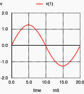
In an ideal power system, the voltage and current supplied to consumers would be a perfect sinusoidal waveform at a single fundamental frequency—50 Hz in the UK and most of Europe, and 60 Hz in North America.
A pure sinusoidal waveform means that:
- The waveform contains only one frequency component, the fundamental.
- The voltage rises and falls smoothly in a continuous, repetitive pattern.
- There are no irregularities, spikes, flat tops, or distortions.
Time period T = 1/f = 1/50 = 0.02 seconds = 20ms
For a 50 Hz system this means that:
- Every 20 ms, the waveform completes one full cycle (positive half-cycle + negative half-cycle).
- In one second, exactly 50 such cycles occur.
Watch Video – Harmonic analysis example
2. Characteristics of an Ideal Sinusoidal Waveform:
A pure sine wave has:
- Smooth and symmetrical shape
- Zero distortion
- No additional frequency components
- Perfectly repeated positive and negative peaks
- Zero DC offset
Such a waveform is shown in Figure 1 (pure sine wave).
Why Pure Sinusoidal Waveform Matters? Because a distortion-free, sinusoidal supply ensures:
- Minimal heating in equipment
- Lower losses in transformers and motors
- Stable operation of protection relays
- Less interference with communication systems
- Reliable performance of inverters and sensitive electronics
This is why national and international standards (e.g., ENA EREC G5/5, IEC 61000) define strict limits for harmonic distortion.
Figure 1 – Sinusoidal waveform for 50 Hz Signal
3. Real-World Power Systems Are Not Perfect
In practical power networks—including the UK grid—a perfectly pure sinusoidal waveform does not exist due to several reasons:
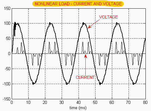
3.1 Non-linear Loads
The following devices draw current in pulses rather than smoothly, introducing harmonics.:
- Variable speed drives (VSDs)
- Inverters (BESS, solar PV, wind turbines)
- UPS systems
- LED lighting
- HVDC converters
Figure 2 – Example of Current and Voltage waveform of non-linear load
3.2 Power Electronic Interfaces
Modern renewable energy systems rely heavily on inverters, which naturally inject higher-order frequency components unless they are properly filtered.
3.3 System Impedances
Every transformer, cable, and line has a frequency-dependent impedance which distorts the waveform under varying load conditions.
3.4 Network Interactions
Multiple harmonic sources feeding into the same grid can interact, amplifying certain harmonic orders through resonance.
Video Lesson – Harmonic analysis example in ETAP
4. What Replaces the Pure Sine Wave? — Harmonics
Because of the above factors, the actual waveform becomes a sum of multiple frequencies, not just the 50 Hz fundamental. Using Fourier series, any distorted periodic wave can be represented as:
![]()
Where:
- V1 = fundamental component
- V3, V5, V7… = harmonic components of 150 Hz, 250 Hz, 350 Hz, etc.
These additional frequency components create waveform distortion. The higher the harmonic content, the less “smooth” and more distorted the waveform becomes.
Figure 3 – Graphical illustration of harmonics

5. What are Harmonics
In electrical power systems, the term harmonics refers to frequency components of a waveform that are integer multiples of the fundamental frequency (50 Hz in the UK). Harmonics arise when the original sinusoidal waveform becomes distorted due to non-linear loads or power electronic devices.
To understand harmonics, we can use an analogy from fault analysis:
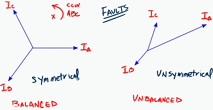
5.1 Analogy: Symmetrical Components
When analyzing unbalanced three-phase systems, we break an unbalanced set of phase voltages into:
- Positive sequence
- Negative sequence
- Zero sequence
This mathematical decomposition converts a complex, unbalanced problem into three simple, balanced systems that are easier to study.
Figure 4 – Balanced Vs Unbalanced system
5.2 The Same Concept Applies to Distorted Waveforms
If a voltage or current waveform is not a pure sine wave, it can be decomposed into a set of perfectly sinusoidal frequency components. This process is based on Fourier series, which states: Any periodic but distorted waveform can be represented as the sum of multiple sine waves of different frequencies and amplitudes.
These frequency components are harmonics.
5.2.1 How Harmonics Are Defined
If the fundamental frequency is 50 Hz, then:
- 2nd harmonic = 2 × 50 = 100 Hz
- 3rd harmonic = 3 × 50 = 150 Hz
- 5th harmonic = 5 × 50 = 250 Hz
- 7th harmonic = 7 × 50 = 350 Hz
- … and so on.
Thus:
Harmonic Order (h) = h × ffundamantal
Where h is an integer (2, 3, 4, 5…). Each harmonic is a clean sinusoidal wave—just at a different frequency.
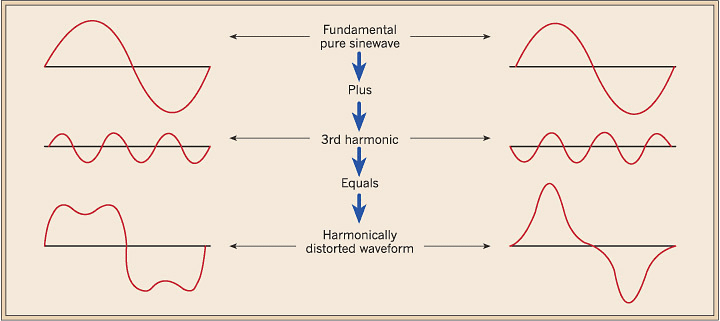
5.2.2 Decomposition of Distorted Waveform
A distorted waveform looks irregular, but mathematically it can be broken into:
- The fundamental component (50 Hz)
- Multiple harmonic components (150 Hz, 250 Hz, 350 Hz…)
The sum of these individual sine waves accurately reconstructs the distorted waveform. This concept is crucial because it allows engineers to study a complex, distorted waveform in terms of simple sinusoidal components.
Figure 5 – Impact of harmonics on sinusoidal waveform
6. Why to Study and Investigate Harmonics?
Harmonics introduce additional frequency components into the electrical network, which deform the ideal sinusoidal waveform. These distorted voltages and currents cause a wide range of technical and operational problems for equipment, networks, and grid stability.
As the penetration of power electronic devices—such as inverter-based renewable generators, EV chargers, and VSDs—continues to rise across UK networks, controlling harmonic levels has become increasingly critical.
Below are the major impacts of harmonics:
6.1 Equipment Overheating
Harmonic currents increase the RMS value of current flowing through equipment such as:
- Cables
- Switchgear
- Motors
- Generators
- Transformers
Because heating is proportional to I2R, even a small increase in harmonic currents can result in significantly higher thermal stress. This leads to:
- Premature insulation failure
- Reduced equipment life
- Unexpected outages
Related electrical guides & articles


Muhammad Kashif
Muhammad Kashif Shamshad is an Electrical Engineer and has more than 17 years of experience in operation & maintenance, erection, testing project management, consultancy, supervision, and commissioning of Power Plant, GIS, and AIS high voltage substations ranging up to 500 kV HVAC & ±660kV HVDC more than ten years experience is with Siemens Saudi Arabia.Profile: Muhammad Kashif
