
Estimated Study Time: 7 minutes
Rotating Magnetic Field
The fundamental principle of operation of AC machines is the generation of a rotating magnetic field, which causes the rotor to turn at a speed that depends on the speed of rotation of the magnetic field.
 Rotating Magnetic Field in AC machines
We’ll now explain how a rotating magnetic field can be generated in the stator and air gap of an AC machine by means of alternating currents.
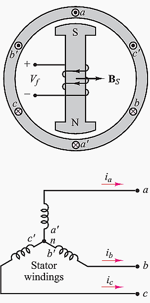
Consider the stator shown in Figure 1, which supports windings a-a′, b-b′ and c-c′. The coils are geometrically spaced 120◦ apart, and a three-phase voltage is applied to the coils. The currents generated by a three-phase source are also spaced by 120◦, as illustrated in Figure 2 below.

The phase voltages referenced to the neutral terminal would then be given by the expressions //

where ωe is the frequency of the AC supply, or line frequency. The coils in each winding are arranged in such a way that the flux distribution generated by any one winding is approximately sinusoidal.
Such a flux distribution may be obtained by appropriately arranging groups of coils for each winding over the stator surface. Since the coils are spaced 120◦ apart, the flux distribution resulting from the sum of the contributions of the three windings is the sum of the fluxes due to the separate windings, as shown in Figure 3.

Thus, the flux in a three-phase machine rotates in space according to the vector diagram of Figure 4, and the flux is constant in amplitude. A stationary observer on the machine’s stator would see a sinusoidally varying flux distribution, as shown in Figure 3.

Since the resultant flux of Figure 3 is generated by the currents of Figure 2, the speed of rotation of the flux must be related to the frequency of the sinusoidal phase currents. In the case of the stator of Figure 1, the number of magnetic poles resulting from the winding configuration is 2.
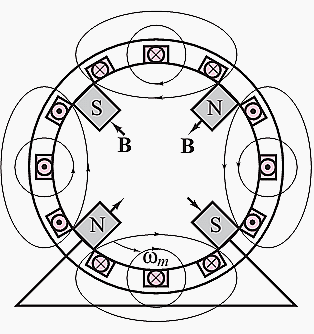
However, it is also possible to configure the windings so that they have more poles. For example, Figure 5 depicts a simplified view of a four-pole stator.
In general, the speed of the rotating magnetic field is determined by the frequency of the excitation current f and by the number of poles present in the stator p according to

where ns (or ωs) is usually called the synchronous speed.
Now, the structure of the windings in the preceding discussion is the same whether the AC machine is a motor or a generator. The distinction between the two depends on the direction of power flow. In a generator, the electromagnetic torque is a reaction torque that opposes rotation of the machine; this is the torque against which the prime mover does work.
As described aabove, the stator magnetic field rotates in an AC machine, and therefore the rotor cannot “catch up” with the stator field and is in constant pursuit of it.
The speed of rotation of the rotor will therefore depend on the number of magnetic poles present in the stator and in the rotor.
The magnitude of the torque produced in the machine is a function of the angle γ between the stator and rotor magnetic fields. Precise expressions for this torque depend on how the magnetic fields are generated and will be given separately for the two cases of synchronous and induction machines.
What is common to all rotating machines is that the number of stator and rotor poles must be identical if any torque is to be generated. Further, the number of poles must be even, since for each north pole there must be a corresponding south pole.
One important desired feature in an electric machine is an ability to generate a constant electromagnetic torque.
With a constant-torque machine, one can avoid torque pulsations that could lead to undesired mechanical vibration in the motor itself and in other mechanical components attached to the motor (e.g., mechanical loads, such as spindles or belt drives). A constant torque may not always be achieved, although it will be shown that it is possible to accomplish this goal when the excitation currents are multiphase.
A general rule of thumb, in this respect, is that it is desirable, insofar as possible, to produce a constant flux per pole.
Interesting video of rotating magnetic field
Reference // Fundamentals of electrical engineering by Giorgio Rizzoni, The Ohio State University (Purchase from Amazon)
Related electrical guides & articles


Edvard Csanyi
Hi, I'm an electrical engineer, programmer and founder of EEP - Electrical Engineering Portal. I worked twelve years at Schneider Electric in the position of technical support for low- and medium-voltage projects and the design of busbar trunking systems.I'm highly specialized in the design of LV/MV switchgear and low-voltage, high-power busbar trunking (<6300A) in substations, commercial buildings and industry facilities. I'm also a professional in AutoCAD programming.
Profile: Edvard Csanyi

Sorry, that Figure 4 is wrong. The field of one phase does not rotate, it is fixed by the axis of the coil; the vector result of the 3 phases’ field rotates.
How make 12v powerful three phase magnetic motor for driving free energy generator
Great information here! Can I ask a quick question about Figure 3? I can see that the individual flux components plotted aren’t 120 degrees apart. How is delay or angular difference between phi_a, phi_b, and phi_c determined? How were those spacings between the three flux components determined? Thanks!!
I wanna to know more about the soft starter three phase induction motors
and the principle of operation of soft starter too