
Estimated Study Time: 23 minutes
Protection & Control Trip Circuits
What are the trip circuits, and what do they do? Well, trip circuits are a small part of the control circuitry that exists within a substation, which provides functionality for protection, control, metering, and monitoring. Reliable design of trip circuits is of special importance, however, because these circuits directly influence overall protection reliability, mistakes are not allowed.
 Rules of Thumb In Substation Control and Trip Circuit Design
Protection and control circuitry within a substation can represent a complex arrangement of wiring that requires considerable effort and care to create, construct, and test. Even after careful layout and testing, wiring problems are often not discovered until misoperations occur during actual operating conditions.
The complex nature of the circuitry sometimes allows for sneak circuits to exist, which are difficult to detect. Testing of the entire control system is difficult because of the extensive area covered by the wiring, interrelationships between different portions of the circuitry, and the fact that some facilities may be in service when tests are being carried out.
The facilities that are associated with trip circuits include DC supply systems, relay output contacts, targeting coils, seal-in devices, auxiliary relays, breaker trip coils, various types of auxiliary switches located within associated breakers, and all the wiring that interconnect these devices.
Even in modern substation designs that use digital communication systems, trip circuits consist of hardwire design as a DC is required to be delivered to the breaker trip coil.
- Substation DC Systems
- Trip Circuit Devices:
- Trip Circuit Design
- Trip Circuit Monitoring and Alarms
- Download Attachment (PDF) 🔗 ‘Practical Handbook for Relay Protection Engineers’
1. Substation DC Systems
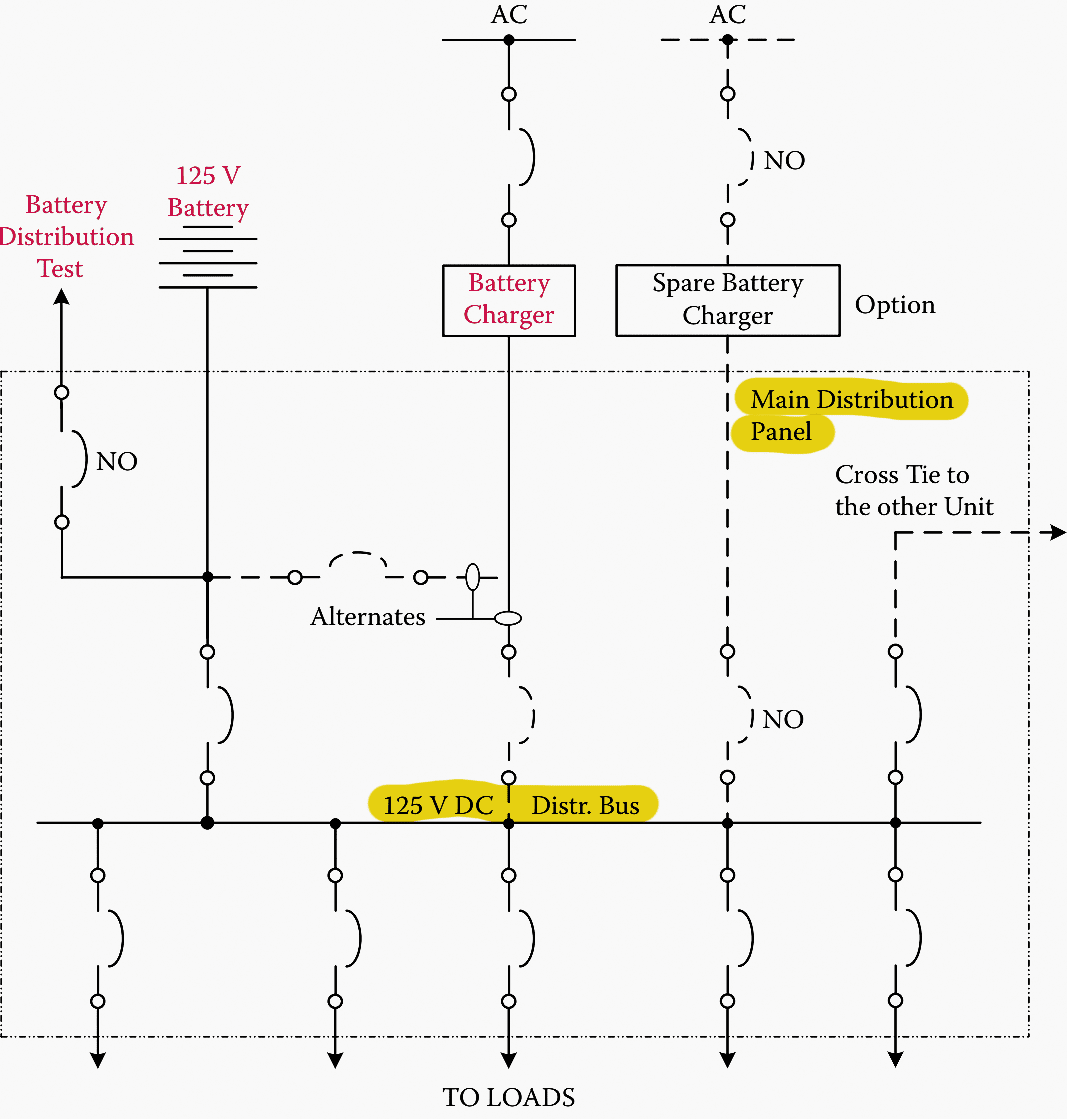
The function of a substation DC system is to provide a reliable source of power for protection and control functions at the station. The DC supply is provided by one or more banks of storage batteries, a battery charger, and a DC distribution panel.
A stored energy source of power is required for this function as auxiliary AC power at the substation may not be available during faults.
It is exactly during such conditions that power is required to power protective devices and to initiate breaker trippings. Typical operating voltages of DC systems are 48, 125, and 250 V. The major loads connected to the DC system are the trip and close coils of circuit breakers, power supplies of electronic relays, meters, and communication equipment, along with a variety of auxiliary relay coils.
The design arrangement of the DC circuits varies depending on the preference of the utility. In one design, a dedicated DC feeder is provided for each breaker and its associated relaying.
A more economical design that is commonly used is a tapped-feeder arrangement. In such a design, a DC feeder is tapped for supply to a circuit breaker trip coil. The individual tapped circuits are usually fused. When a breaker is equipped with dual trip coils, each coil is supplied from a different tapped circuit.
Tapped circuits that supply a breaker trip coil may also be used to supply relaying associated with the breaker.
It is common practice, however, to use separate circuits to supply primary, backup, and breaker failure relaying.
Figure 1 – 125 V DC supply system diagram
Some utilities prefer not to fuse the tapped DC feeders if the loss of the main DC circuit would not reduce reliability of protection beyond desired levels. Figure 2 illustrates a possible arrangement for a fused tapped-feeder DC system.
Regardless of what arrangement is used for the DC system, a major design objective is that the system should incorporate a similar level of reliability that is provided for overall system protection. In some cases, although redundant relaying systems are provided, only a single battery bank is used.
This practice is based on the relatively high cost of battery systems, and the very high level of reliability that experience has shown can be obtained from battery banks when good maintenance and monitoring practices are employed.
Figure 2 – Typical arrangement of a DC supply using feeders tapped through a fuse
2. Trip Circuit Devices
Various devices are connected to tripping control circuits that serve to protect other elements in the circuit or to provide logic and initiate actions required for the circuit to deliver its desired functions. Such devices include auxiliary relays, surge protectors, target and seal-in devices, breaker trip coils, and switches.
2.1 Auxiliary Relays
Auxiliary relays are used in control circuits to initiate closings or openings in other paths of the control circuitry. For example, in trip circuits, operation of a protective relay often initiates operation of an auxiliary relay, which, in turn, allows a path to be created that allows DC to flow through a trip coil. Construction of auxiliary relays may be electromechanical or static.
Electromechanical auxiliary relays usually take considerable time to operate, which must be taken into account when applied. Time delays for electromechanical auxiliary relays can vary from about 0.25 to 2.0 cycles.
Static auxiliary tripping relays usually incorporate an silicon controlled rectifier (SCR) in the tripping circuit along with hand-reset mechanical targets, target lamps, and telephone-type auxiliary relays for initiating other required logic.
In digital control systems that use programmable controllers and digital communication systems, the function of auxiliary relays can be incorporated into the associated control software.
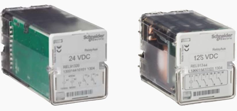
Figure 3 – Left: Trip circuit supervision relay; Right: Auxiliary supply circuit supervision relay
2.2 Targeting and Seal -In Devices
Most protective relays incorporate a targeting feature that provides indication at the relay location that the relay had operated to trip the related circuit breaker(s). Targets provide valuable information for analyzing the nature of the tripping event.
However, the target must be reset manually at the relay location although targets on modern microprocessor relays may be capable of being reset from a remote location through a digital communication channel.
A seal-in device is a contact that bypasses the output contact of a protective relay. Action to close the seal-in contact is usually initiated by trip current flow.
Sometimes the same coil that allows a target to indicate also closes the seal-in contact. The seal-in contact is not allowed to drop out until the associated breaker(s) that has been tripped is open and trip current has been interrupted by breaker auxiliary contacts.
A typical seal-in coil connection is shown in Figure 4.
Figure 4 – Trip circuit illustration showing connection of seal-in coil and associated contacts
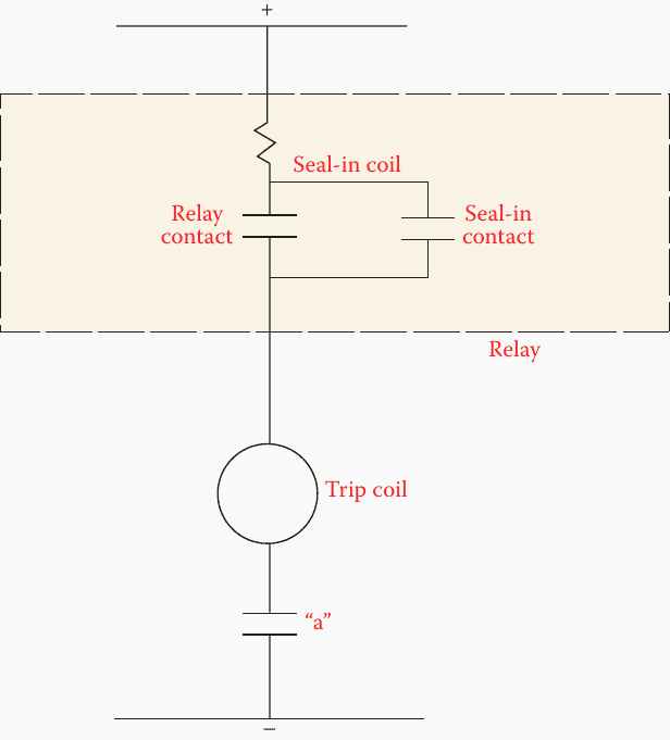
The purpose of the seal-in contact is to protect the relay contact from damage if it should attempt to interrupt the DC trip currents. The relay contacts are delicate and are not designed to interrupt the DC trip current. The seal-in contact also keeps closure of the trip circuit intact in the event of the relay contacts chattering.
Target and seal-in coils are rated to match the characteristics of the DC system into which they are connected. On electromechanical relays, the target/seal-in coil pickup current can be set to match the expected current drawn by the circuit.
Target/seal-in coils are generally located inside the relay and are provided as a part of the relay.
Watch Video Lesson – Seal-in circuit
2.3 Switches and Diodes
Manually operated switches may be connected into trip circuits. Such switches are installed to cut out relays, contacts, or portions of the trip circuit to facilitate testing or to remove a relay from service subsequent to a misoperation. Design practices with regard to the use of switches in trip circuits vary among utilities.
The advantage of such switches is that they can make testing more safe and efficient. The disadvantage is that if such switches are left in the improper position, protection may not be available when needed.
The disadvantage of using diodes is that they are subject to failure, which can remain undetected until a misoperation occurs.
Watch Video Lesson – Battery charger single-line diagram (diode & switches)
2.4 Trip Coils
The function of trip coils is to initiate action to open the main contacts of breakers. The actual energy to open the contacts is provided by some form of stored energy such as springs, compressed air, and high-pressure gas. Trip coils therefore do not directly open the contacts, but act to release a latch or open a valve that allows the release of some form of stored energy used to move the contacts.
Breaker designs can vary considerably among manufacturers, and it is important for protection engineers to understand the characteristics of the trip coils and other control devices used in the specific breaker that is used, so that proper trip circuit designs can be developed.
Figure 5 – Picture of the solenoid (Tripping coil) used in the circuit breaker

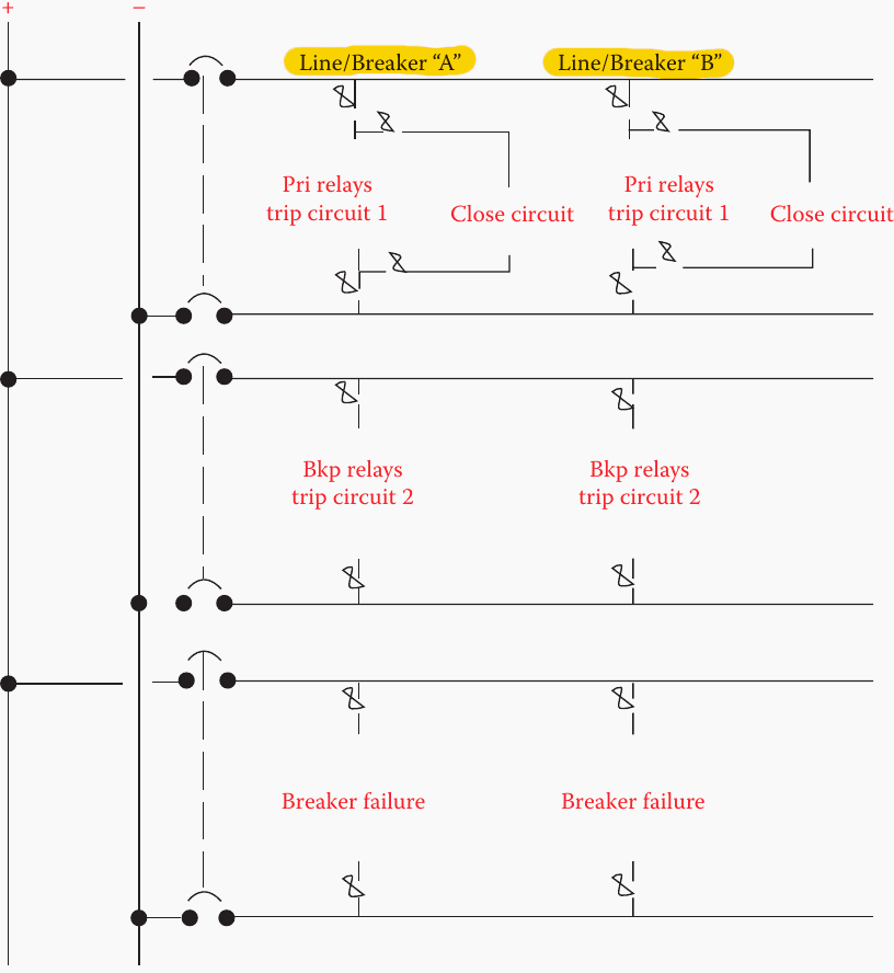
3. Trip Circuit Design
Trip circuits may be required to trip a single breaker or multiple breakers. Tripping of a single breaker is usually associated with distribution feeders, subtransmission lines, and industrial circuits. Multiple breakers need to be tripped with bus arrangements such as breaker-and-a-half, ring bus, or double bus–double breaker designs.
Such designs are usually associated with higher-voltage systems.
Regardless of the design details, some general requirements that need to be addressed when developing designs for trip circuits are as follows:
Requirement #1 – Adequate voltage must be delivered to the trip coil(s) to assure reliable breaker operation. All possible voltage drops that may exist in the circuit must be considered when determining voltage available at the trip coil(s).
Requirement #2 – Sufficient DC current must be available to operate targets on all relays that have operated. Proper tap settings and coil ratings need to be selected for target and seal-in units.
Requirement #3 – Care must be taken to avoid connections between DC circuits. Such connections can result in the loss of both primary and backup relays for a single failure on the DC system.
Requirement #4 – Currents drawn by auxiliary relays must not cause incorrect operation of seal-in units or the failure of such units to drop out properly.
Requirement #5 – Protection against surges caused by the operation of the various coils that exist in the control circuitry should be applied to protect other equipment connected in the circuit.
Requirement #6 – Relay coils should be connected to the negative DC bus. This is required to minimize the potential failure of such coils because of a buildup of corrosion.
Coils that are directly connected to the positive DC bus are subject to corrosion with the presence of moisture.
Practical Course – MV Switchgear Schematics Course: Tripping, Trip Circuit Supervision, Interlocking and Indication Circuits
4. Trip Circuit Monitoring and Alarms
Supervision of control circuitry that affects the ability of tripping functions to perform properly is an important enhancement for protection reliability. Important conditions for which monitoring should be considered include the following:
- Problems in the DC tripping system—such as battery problems, open breaker
trip coil, blown fuse in DC circuit, or an open in the DC circuit wiring. - Loss of AC potential to primary and backup relaying.
- Loss of communication channels that are used to initiate tripping.
- Relay problems when self-checking features are available.
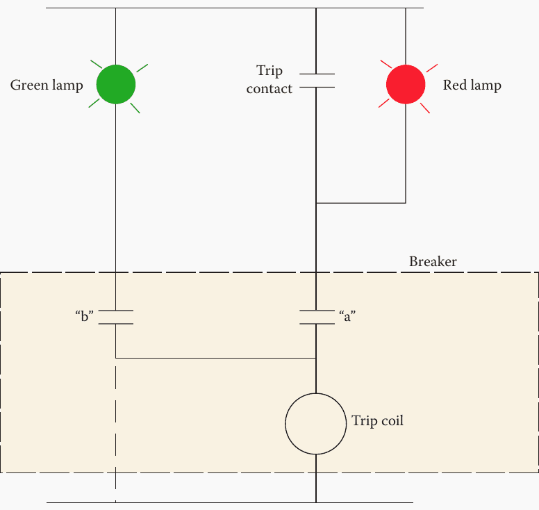
A common means for monitoring availability of DC tripping voltage is by connecting lamps in the DC tripping circuit. A simple arrangement for connecting such lamps in a trip circuit is illustrated in Figure 6.
The lamps that are used must meet requirements of the DC circuit into which they are installed and should provide a feature to easily check for burnt-out lamps. Alarm relays may be used in addition or in place of the lamps. Such application allows for sending alarms to remote locations, which is highly recommended for unattended substations.
Figure 6 – Illustration of lamps used for monitoring in DC trip circuits
Low DC voltage or inadequate energy in the battery bank is more difficult to detect than a complete loss of DC voltage. Undervoltage relays are sometimes applied along with devices that monitor the operating status of the battery charger. Battery systems require that periodic maintenance be performed on a regular basis.
Specific gravity tests should be included to verify the integrity of the individual cells in the battery bank.
Modern substations with digital control systems employ various electronic methods for providing monitoring and alarming for various functions. Modern microprocessor-based relays contain self-checking ability, which provides local indication, remote alarming, and the blocking of relay operation for certain failures.
A simple design may include several overcurrent elements. A design that is little more complex may add automatic reclosing functions along with the overcurrent elements. As noted earlier, a more complex relay may include all functions required for protecting a specific power system facility along with logic to provide control for the facility.
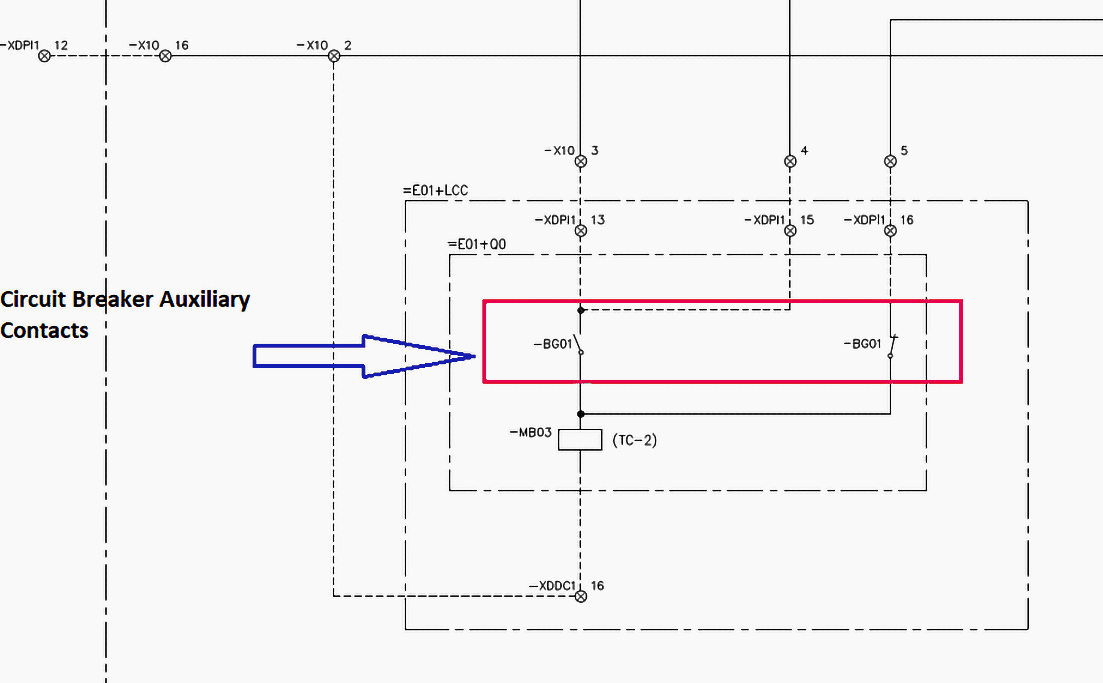
Figure 7 – BG01 are the Circuit breaker auxiliary contacts used for the trip circuit supervision
10. Attachment (PDF): Practical Handbook for Relay Protection Engineers
Download: Practical Handbook for Relay Protection Engineers (for premium members only):
Source: Protective Relaying: Principles and Applications by J. Lewis Blackburn, Thomas J. Domin
Related electrical guides & articles


Edvard Csanyi
Hi, I'm an electrical engineer, programmer and founder of EEP - Electrical Engineering Portal. I worked twelve years at Schneider Electric in the position of technical support for low- and medium-voltage projects and the design of busbar trunking systems.I'm highly specialized in the design of LV/MV switchgear and low-voltage, high-power busbar trunking (<6300A) in substations, commercial buildings and industry facilities. I'm also a professional in AutoCAD programming.
Profile: Edvard Csanyi
