
Estimated Study Time: 19 minutes
What’s the catch: The microshock
This technical article analyzes the safety requirements against indirect contact employed in particularly special medical locations (e.g., hospitals, medical, and dental practices, etc.), where environmental conditions may increase the risk of indirect contact and therefore the electroshock, precisely microshock.
 The ground is not just ground! At least not in hospitals, medical, and dental practices
Generally speaking, special locations and installations are locations where the presence of water or moisture decreases the resistance-to-ground of the person’s body by lowering his/her skin resistance. Special locations in terms of safety requirements against indirect contact are also wet locations where the humidity can increase the failure rate of equipment by compromising the integrity of its basic insulation.
In medical locations (e.g., hospitals, medical, and dental practices, etc.), patients are exposed to increased hazard of electric shock due to their particular conditions. Patients, in fact, may be unconscious, or anaesthetized and, therefore, unable to let-go of an energized part.
In addition, patients may be connected to medical equipment either through applied parts to the skin (e.g., sensors, electrodes, etc.), often locally treated to lower its resistance, and/or through the introduction of catheters directly into their body’s organs (e.g., the heart).
In these conditions, the current is no longer limited by the body resistance-to-ground, because this resistance does not form part with the fault-loop. Patients become particularly susceptible to the adverse effects of electricity, and currents of magnitude of a few tens of microamperes can trigger ventricular fibrillation.
This phenomenon is defined as microshock.
- High Protective Conductor Currents
- Leakage Currents
- Local Equipotential Earthing Connection
- Electrical Separation
1. High Protective Conductor Currents
Medical electronics equipment may be sensitive to electromagnetic interferences irradiated by “disturbing” loads. For this reason, radio frequency input filters constituted by capacitors connected between supply conductors and enclosures of equipment are employed to enhance the electronic systems’ immunity.
Such filters may cause continuous leakage currents through the protective conductors in excess of 3.5 A. See Figure 1.
Figure 1 – Earth leakage currents due to radio frequency filters
IEC 60950-13 limits the maximum value of leakage currents of Class I, stationary, or pluggable, equipment to 5% of the input current. The presence of high currents on protective conductors might cause nuisance trippings of RCDs, when their residual settings are exceeded even in the absence of ground faults.
Serious hazard is caused by the accidental loss of the protective conductor serving the equipment.
See Figure 2.
Figure 2 – Hazardous situation caused by the accidental loss of the PE
The leakage current, in fact, will circulate through the person’s body if she/he comes into contact with the enclosure. Thus, for safety reasons, the bonding of high leakage current equipment must be assured by enhancing the reliability of the PE. This can be obtained by doubling its cross-sectional area, with respect to minimum permissible values, by using more than one PE conductor in parallel, and/or monitoring its electrical continuity.
If the leakage current exceeds 3.5 A, the aforementioned IEC standard requires a warning label to be affixed adjacent to the equipment power connection, indicating the necessity of connecting the protective conductor before switching on the supply.
See Figure 3.
Figure 3 – Grounding electrodes for sensitive 50/60-Hz electronic equipment
The above arrangement is extremely unsafe and must be avoided, because it does not assure equal potential between equipment under fault conditions. In the case of ground faults on either exposed conductive part, persons in simultaneous contact with both pieces of equipment are subject to the whole earth potential.
Each exposed conductive part becomes, in fact, an extraneous conductive part to the other one. In addition, separate earthing points, possibly energized at different potentials under fault conditions, can cause circulation of ground currents, and be the source of the electrical noise one wants to eliminate.
Alternatively, a separation transformer with RCDs on the primary side can be used to supply the load, as RCDs would not sense any leakage currents on its secondary side.
Suggested Reading – Current sensors as the eyes of RCD & tips for their correct installation
Current sensors as the eyes of RCD and tips for their correct installation
Go back to the Contents Table ↑
2. Leakage Currents
Ordinary Class I equipment, medical or not, during its use may leak current through the insulation, and into the protective conductor. As discussed in previous Section 1, in the case of interruption of the protective conductor, the leakage current may circulate through the persons in contact with the enclosure.
For ordinary equipment (i.e., equipment having low protective conductor currents), the magnitude of such current is so low that it does not constitute a hazard for persons.
In Figure 4, it is shown how in a single fault condition, the patient leakage current IP can directly circulate through his/her heart due to contacts with any Class I equipment (Ien) and/or due to applied parts to the body (Iap).
In the above situation, the person is at great risk of microshock, as the patient current may exceed the fibrillation threshold.
Figure 4 – Patient leakage current caused by the interruption of the PE

Go back to the Contents Table ↑
3. Local Equipotential Earthing Connection
In addition to the “chronic” problem of leakage currents from regularly operating Class I equipment emphasized by the interruption of their protective conductors, the safety of the patient can also be endangered by actual ground faults.
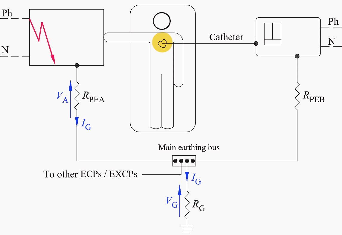
Figure 5 exemplifies a ground fault in TT systems because of the failure of an electrical component in the patient vicinity. The patient vicinity is defined as the space with enclosures likely to be touched by the patient, which extends 1.83 m beyond the perimeter of the bed and 2.29 m above the floor.
In the above situation, a potential difference VA, caused by the voltage drop on the protective conductor of resistance RPEA, appears between the two pieces of equipment the patient may be in simultaneous contact with by touch and via catheters.
Figure 5 – Hazardous condition in the presence of a sound PE
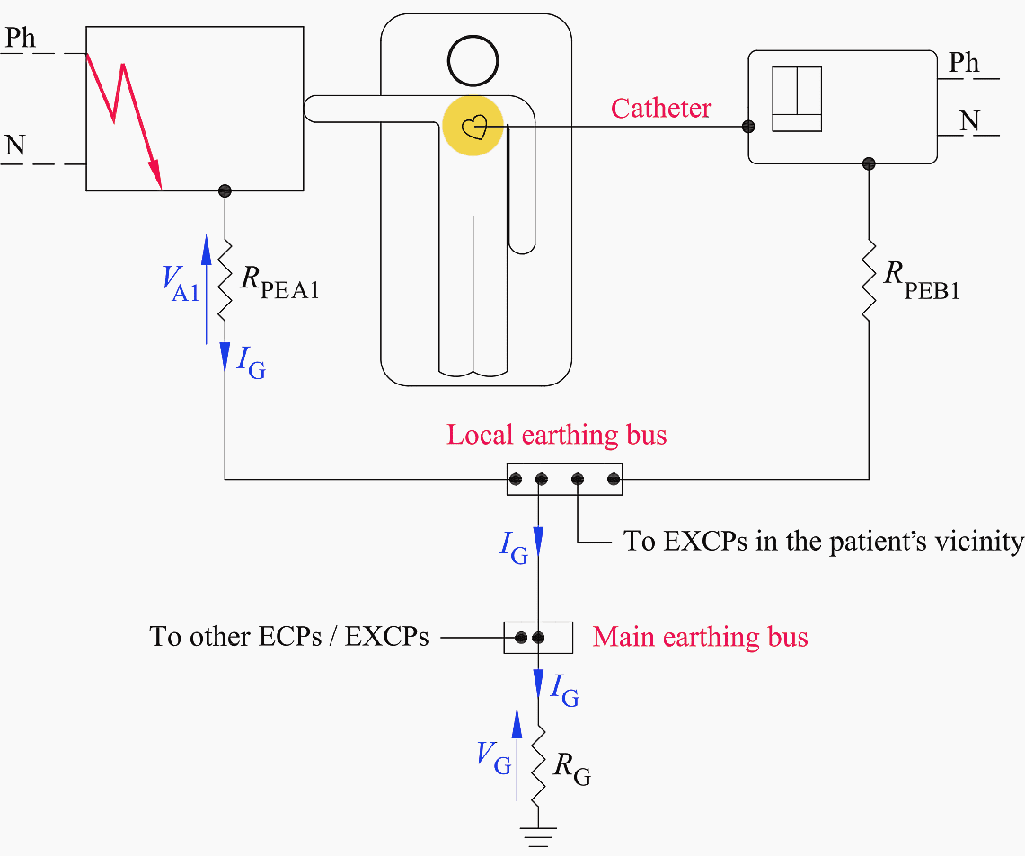
The reduction of such voltage drop can be obtained by connecting together all the exposed conductive parts (ECPs) and the extraneous conductive parts (EXCPs) to a local equipotential earthing bus located within the patient vicinity (see Figure 6).
This supplementary equipotential bonding connection lowers the resistance of the protective conductor serving the faulty exposed conductive part, ECP (i.e., RPEA1 < RPEA), thereby decreasing the touch voltage (i.e., VA1 < VA).
In these assumptions, the resulting resistance-to-ground of any metal part in the patient vicinity must exceed 500 kΩ in order not to be an extraneous conductive parts (EXCPs), and therefore, not bonded to the local earthing bus.
Figure 6 – A local equipotential earthing bus reduces the voltage drop on the PE
Go back to the Contents Table ↑
4. Electrical Separation
The local supplementary bonding connection, even though within the patient vicinity, cannot always sufficiently decrease the resistance of the PE and therefore limit the touch voltage to safe values. This is true especially in TN systems, where the ground-fault current may be rather high and so may the voltage drop on the PEs.
In non-fault conditions, instead, currents leaking from pieces of equipment connected to the same local earthing bus are virtually identical and in phase, and cause almost identical voltage drops over their PE, thereby determining no appreciable potential differences.
First faults occurring in electrically separated systems, cause the flow of capacitive currents IG of low magnitude (i.e., order of milliamperes) through the PEs. As a consequence, the touch voltage the patient might be exposed to is well within safe limits.
Problems may arise at the occurrence of a subsequent second fault involving the other pole in another piece of equipment in contact with the patient. In that case, the resulting short circuit current circulating through the protective conductors might cause dangerous potential differences between the faulty exposed conductive parts, even in the presence of the supplementary equipotential bonding.
For this reason, in medical locations, the first fault must be promptly traced by means of an insulation-monitoring device and then cleared.
Figure 7 – Isolating transformer supplying the circuits in the patient vicinity

The earthing connection of the enclosures of the separated system, shown in Figure 7, makes this system resemble the IT system. In the patient vicinity, in fact, there may be small equipment, not supplied by the isolating transformer, requiring the ground connection available at the local earthing bus.
The above arrangement is a violation of the general rule, which prohibits the exposed conductive parts of separated systems to share the earth with nonseparated systems (prohibition also applicable to Class II equipment).
In the presence of the supplementary equipotential bonding in medical locations, this risk is, indeed, very low and deemed acceptable. In fact, even if the earthing bus attains a certain potential under fault conditions, all the ECPs in the patient vicinity will simultaneously reach this same value, as Figure 7 shows; ergo, no potential differences can appear among them and the patient is safe.
As a consequence, the grounding connection in separated systems adopted in medical locations is deemed safe in the presence of the local equipotential bonding.
Suggested course – Learn AC Distribution Panel Drawings: Single-Line Diagrams, Wirings, and Interlocking Schematics
Learn AC Distribution Panel Drawings: Single-Line Diagrams, Wirings, and Interlocking Schematics
Go back to the Contents Table ↑
4.1 Interruption of the Protective Conductor in Separated Systems
The interruption of the PE is dangerous even in separated systems because the resulting capacitive current through the patient may exceed the fibrillation limits (Figure 8).
Let Z1, Z2, Z3, and Z4 be the capacitive impedances-to-ground of supply and equipment, as indicated in Figure 8. Upon loss of the protective conductor, the leakage current impressed by pole D through Z4 will reclose toward pole A by circulating through the patient.
Figure 8 – Separated system with interrupted PE

The above impedances are connected in a “bridge” configuration across whose diagonal BC patients may find themselves linked (Figure 9).
Figure 9 – The patient may be connected across the impedance bridge’s diagonal
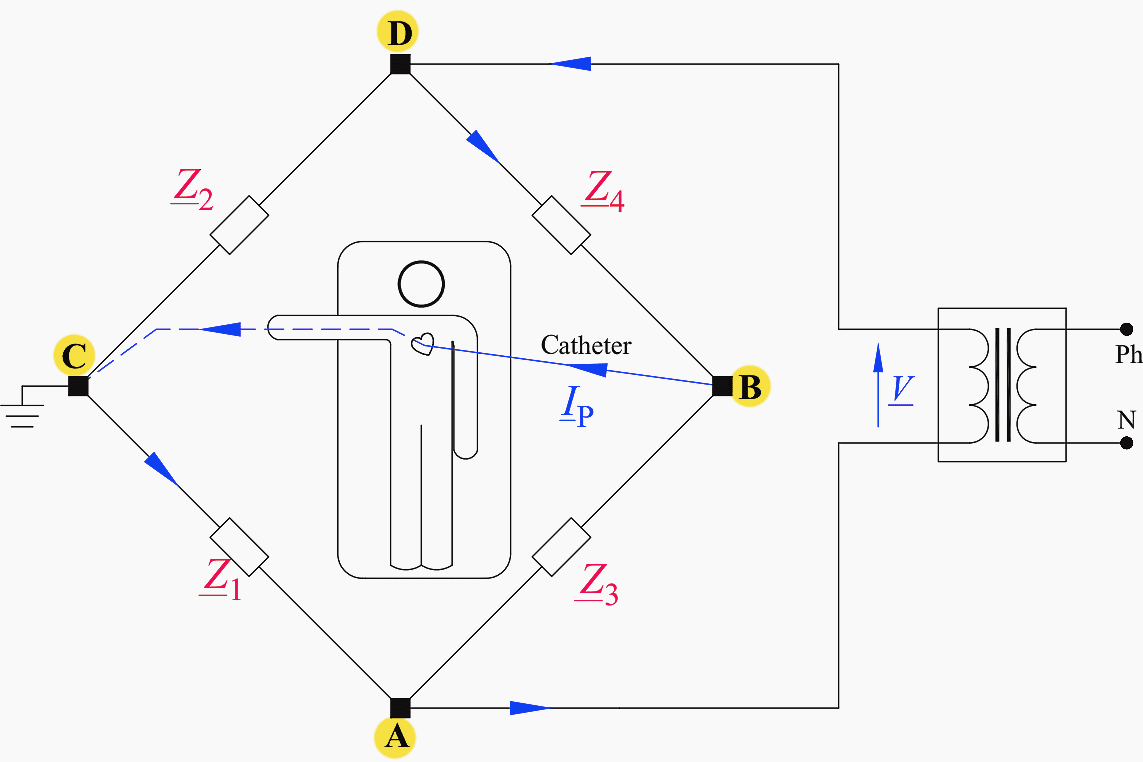
If the impedance bridge is balanced, that is, Z1×Z4 = Z2×Z3, the patient is safe, as VBC = IP = 0. If the bridge is not balanced, the patient current IP can be obtained by deducing the Thevenin equivalent circuit as seen at the points B and C.
See Figure 10.
Figure 10 – Thevenin equivalent circuit as seen at the points B and C of the bridge

The equivalent Thevenin voltage Vth is calculated by applying Kirchhoff’s second law to the loop DBAD and the voltage divider rule (Equation 1):
The Thevenin impedance Zth is given by:

Thus, the patient current IP is:

where RB is the patient’s body resistance.
In balance conditions of the bridge (i.e., Z1×Z4 = Z2×Z3), it appears clear from Eq. (15.2) that Vth equals zero; therefore, the patient is safe even if the protective conductor of the medical equipment is interrupted.
Thus, designers cannot rely upon balanced bridges to achieve safety in medical locations.
Suggested Course – Transformer Differential Protection Course: Understanding Schematics, Relay Settings and Testing
Transformer Differential Protection Course: Understanding Schematics, Relay Settings and Testing
Go back to the Contents Table ↑
Source: Electrical Safety of LV Systems by Dr. Massimo A. G. Mitolo
Related electrical guides & articles


Edvard Csanyi
Hi, I'm an electrical engineer, programmer and founder of EEP - Electrical Engineering Portal. I worked twelve years at Schneider Electric in the position of technical support for low- and medium-voltage projects and the design of busbar trunking systems.I'm highly specialized in the design of LV/MV switchgear and low-voltage, high-power busbar trunking (<6300A) in substations, commercial buildings and industry facilities. I'm also a professional in AutoCAD programming.
Profile: Edvard Csanyi

I feel many thanks.
Professional reading to enhance and expand my knowledge and understanding of topics, themes and research.
You went to extraordinary lengths explanation to understand.
Terima Kasih