
Estimated Study Time: 20 minutes
SCADA, RTUs, PLCs, servers…
To explain in very simple words, I would say that SCADA is a bunch of equipment that provides an operator at a remote location with sufficient information to determine the status of particular equipment/process and make actions without being physically present.
 Five major SCADA components you MUST know about
SCADA implementation thus involves two major activities: data acquisition (monitoring) of a process or equipment and the supervisory control of the process, thus leading to complete automation.
The complete automation of a process can be achieved by automating the monitoring and the control actions.
The architecture shown in Figure 1 illustrates a typical SCADA system in terms of the components or elements which are interconnected via a communication network.
Following the illustration are more detailed explanations of each of the major components.
Let’s described in more detail these five major ingredients of a SCADA system, as listed below:
- Field Devices and Signals
- Programmable Process Controllers (RTUs, PLCs)
- SCADA Operations User Workstation
- SCADA Server Computer
- Communication Network
1. Field Devices and Signals
The icons in the illustration labelled ‘Device’ represent individual signals. These may be discrete or analog, input to the PLC or output from the PLC. When designing the software for a SCADA system, the various field signals and/or devices must be considered in terms of what information is to be monitored and what equipment is to be controlled.
When designing SCADA software, all of the field signals must be identified for each process area. As shown above, the field devices are wired into the various PLCs/RTUs, which in turn process the signals.
All of the field devices, which are represented by discrete and analog signals, are connected to the various input and output modules of the PLC/RTU. It processes the input signals and effects control through the output signals, based upon the programming in the PLC/RTU itself.
Discrete signals can be both input and output types. Such signals are two state, meaning the signal can only be in one of two states at any time. Discrete input signals may include: open and close limit switches, photocell sensors, pushbuttons and selector switches. Discrete output signals may include pilot lights, motor control relays, solenoid valves and valve controls.
Analog signals can also be both input and output types and such signals can have a range of values between two preset limits, most often zero and some maximum value.
Analog input signals may include levels, flowrates, motor speeds, voltage and current from power monitors, water quality signals, and temperatures and pressures. Analog output signals may include motor speed controls for Variable Speed Drives (VSDs) on variable speed motors, valve positioning signals for modulating valves and analog display devices.
SCADA software must consider all of the equipment and signals to be processed.
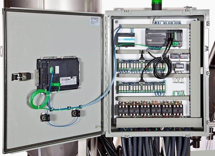
2. Programmable Process Controllers (RTUs, PLCs)
A given application for a SCADA system is divided into process areas. Each such area has clearly defined operations to be performed.
For example, a pumping station may use two or three pumps, operating in a lead/lag/standby mode. The automation program in the controller is configured to operate the pumps based upon operator-entered set-points and duty assignments.
Each process area identified within a SCADA system will require its own programmable process controller.
The software designer must allocate the various field I/O signals identified in the previous topic to the required modules in the PLC/RTU. With the list of signals, organized into discrete input, discrete output, analog input and analog output, a count of the number of each type of signal can be determined.
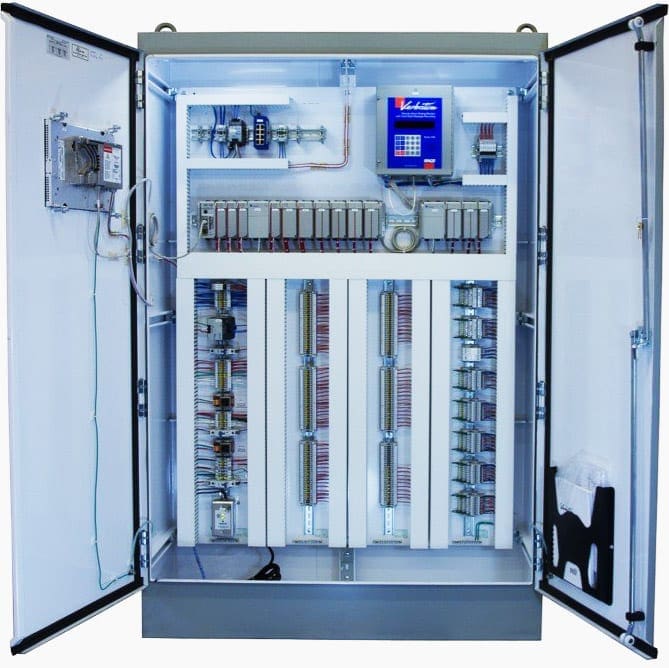
From there, the necessary input/output modules can be determined and configured for the PLC. Depending upon the number of signals, a PLC may consist of multiple racks or chassis of modules.
From the perspective of the application program, however, the software recognizes all modules as though they all reside in a single long rack.
Each of the programmable controllers requires programming in one or more forms.
For example, languages include: Function Block Diagram, Structure Text (High-Level Programming), Sequential Function Chart, and Instruction or Statement List (LowLevel Assembly Programming).
The programmer may choose to use one or more of these languages in a specific PLC application program.
RTU serves as the eyes, ears, and hands of a SCADA system. The RTU acquires all the field data from different field devices, as the human eyes and ears monitor the surroundings, process the data and transmit the relevant data to the master station.
At the same time, it distributes the control signals received from the master station to the field devices, as the human hand executes instructions from the brain.
Today Intelligent Electronic Devices (IEDs) are replacing RTUs.
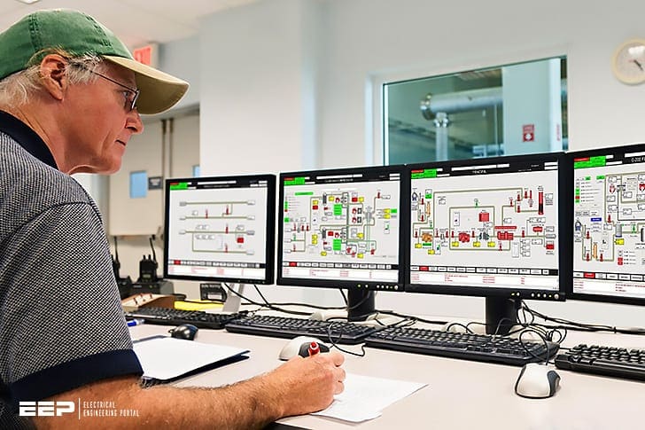
3. SCADA Operations User Workstation
The user operations workstations, usually referred to as the Human Machine Interface (HMI), requires the programming of process graphic displays with animated links to many points in a process database.
Configuration programming is also required to establish the process database, the historical database and the communications interface to the field controllers or the PLCs.
Additional background programs, called scripts, are often used to perform ‘behind the scenes’ operations for the application.
Hence, there are both displays which present the information and ‘behind the scenes’ programming to access the information for the requested display.
In addition, there are often background scripts or programs that are used to perform operations associated with the displays and/or invoke commands to the PLCs, RTUs and other equipment.

4. SCADA Server Computer
Most SCADA systems include at least one, if not two, data server computers. These computers maintain all of the configuration software for the SCADA system.
The server computer is at the physical centre of the Star topology. Historical data collected over time is maintained on the server computer in the form of databases. Current system operating data from all of the field controllers is also maintained in databases on the server computer.
The server computer performs all of the communications with the PLCs and RTUs on the SCADA network. Each RTU/PLC maintains and collects data pertaining to its process areas. This data is then retrieved by the server computer to update the current process and the historical databases.
In small systems, a single workstation can perform the work of both the server and the operations user workstation.
However, if the system has more than one or two programmable process controllers, then the server operations are best assigned to a dedicated workstation, which could serve as an additional user workstation if needed.
Today, many SCADA applications use Relational DataBase Management System (RDBMS) to store, retrieve and report information. Just as the Comma Separated Value (CSV) file, has become a standard method of transferring data between applications, the RDBMS can be accessed using standardized ‘SQL’ commands from any SQL-compliant application.
Another purpose of the SCADA server computer is to provide an interface to other facilities, typically through the Internet, using Firewalls and SQL interface calls.
It is important that the outside access cannot interfere with the internal operations of the SCADA system, so the server computer often provides a secure interface.
Other departments and users may require data collected by the SCADA system, and so a means of accessing this data can be provided through the SCADA server computer, with the appropriate security measures in place.
5. Communication Network
The in-plant equipment, programmable process controllers and SCADA user workstations, are typically interconnected via a Local Area Network (LAN), using Ethernet or other high-speed communication system.
Some SCADA systems may extend outside the physical building into remote sites. These sites require some form of communication back to the host facility also.
Let’s see the brief explanation of the types of network topology, used for SCADA systems.
There are three basic topologies as described below:
- Bus topology
- Star topology
- Token ring topology
5.1 Bus Topology
The Bus Topology as shown in Figure 6, consists of a hardware/software interconnection among all of the nodes in the system.
This architecture resembles a major roadway to and from which all other roads connect. To travel from any one location to any other location requires getting on to this major roadway (network) and then travelling along until an exit to the desired route is found.
All traffic or communications in the system is accomplished via this single bus-type network.

For increased traffic, the network can become overloaded, and the result is a slowing down of the transfer of data from one node to another. While Ethernet over a bus network is generally fast enough, there may be some applications in which this bus topology creates roadblocks to efficient data.
5.2 Star topology
The Star Topology as shown in Figure 3, consists of multiple network paths out from a single master or host node.
Update times to the host node are very fast but does require multiple paths out from the host master node.
The transfer of data between nodes on the Star network does require that the information be passed first from the source node, then through the host node, and then out to the destination node.

5.3 Token ring topology
A Token Ring Topology as shown in Figure 8, works like a ring in which all nodes are interconnected by two network connections. All nodes in the topology are of equal value, and data is passed via this ring from one node to the next.
This topology is predictive in that the speed is constant and the time to transfer data is always at a fixed rate. As the number of nodes in the network increases, the overall data transfer rate drops since there are more nodes through which data must pass to travel from the source node to the destination node.
One possible improvement is to use a combination of topologies in the SCADA network.

Remote communications traditionally used dial-up and then dedicated modems (modulator–demodulator) to transfer data between the remote RTU/PLC and an in-house RTU/PLC.
Within the SCADA software, the communication aspect includes the programming and configuration of various software drivers to allow the SCADA workstations to communicate with the programmable process controllers (RTUs, PLCs), so as to transfer data back and forth.
Interesting SCADA videos
SCADA System Configurations and settings
Tutorial for SCADA Real Time Configuration using wonderware intouch software
What is RTU?
RTU stands for Remote Terminal Unit, sometimes also called Remote Telemetry Unit or Remote Telecontrol Unit. An RTU is a microprocessor-based device that monitors and controls field devices, that then connects to plant control or SCADA (supervisory control and data acquisition) systems.
If you do a search on the definition of an RTU, you may find many results that state an RTU is much more powerful than a PLC as the RTU can have several inputs and outputs.
On the price point, the winner right now is the PLC. PLCs have a lower price point but many consider the RTU to be a much more rugged system which would lead you to believe that spending more initially will equal out in the end.
As far as process control, the RTU is probably on equal ground with the PLC. Both controllers can have multiple different types of I/O, different communications modules, and programming of processes that may require little to no operator intervention.
Where the RTU is considered to have some advantages is in environment tolerances, backup power options, and autonomy.
Sources //
- Designing SCADA Application Software A Practical Approach by Stuart G. McCrady (purchase at Amazon)
- Power system SCADA and smart grids by Mini S. Thomas (Jamia Millia Islamia at University New Delhi, India) and John D. McDonald (GE Energy Management – Digital Energy, Atlanta, Georgia, USA)
Related electrical guides & articles


Edvard Csanyi
Hi, I'm an electrical engineer, programmer and founder of EEP - Electrical Engineering Portal. I worked twelve years at Schneider Electric in the position of technical support for low- and medium-voltage projects and the design of busbar trunking systems.I'm highly specialized in the design of LV/MV switchgear and low-voltage, high-power busbar trunking (<6300A) in substations, commercial buildings and industry facilities. I'm also a professional in AutoCAD programming.
Profile: Edvard Csanyi

great job
Best explanation about dvara used in industry as well as Grid sub stations.
Dear Mr. Edvard
The posts are always very good. I sincerely appreciate and I would to get more knowledge to evaluate how I can implement in my electrical network.
Thanks for share.
Your posts are always very good. I sincerely appreciate and commend your effort. Wish you more grease to your elbows.
The information presented is quite relevant and practical
Is it a must to use multiplexer to connect remote rtu to scada host over microwave radio
I wish to have all your information a bout this program. I would like to study further electrical system!
I just have to appreciate and thank you for this intellectual work of immense impact. Please keep it up. May God be with you.