
Estimated Study Time: 30 minutes
LV Motor Control Center (MCC) Panel
This technical article provides an in-depth engineering analysis of the 1000A Low Voltage Motor Control Center (MCC) panel for high-demand applications. The panel is built on the Prisma M enclosure platform and features a complex array of incoming protection, outgoing motorized feeders, and multiple soft-started motor control circuits. A detailed fault scenario based on the schematics provided for the 1000A MCC is included.
 In-depth Schematics Analysis of the 1000A Low Voltage Motor Control Center (MCC)
A major focus of this design is the incorporation of eight dedicated motor control branches, each utilizing sophisticated soft starters to ensure the smooth, controlled acceleration of heavy mechanical loads.
Furthermore, the panel features complex control logic, continuous grid stability monitoring, and localized power metering to give operators total visibility over energy consumption and system health. To maintain optimal operating temperatures for these power electronics, an active, thermostatically controlled cooling network is strategically implemented throughout the enclosure.
Here is the download link for the complete PDF document with MCC schematics (36 pages). Open it up, so you can follow the discussion.
Schematics (PDF, 1.5 MB)
- MCC General Characteristics and Panel Arrangement:
- Single Line Diagram (SLD) Overview (Pages 5-6):
- Incoming Control and Monitoring (Pages 7-8):
- Outgoing Motorized Feeder Control (Pages 9-10):
- Soft Starter Control Topologies (Pages 11-34):
- Auxiliary Circuits and Thermal Management (Pages 35-36)
- Conclusion
- A Detailed Fault Scenario (How the Protection & Control Logic Work)
- Attachment (PDF) 🔗 Technical Specifications & Drawings For 132 kV Outdoor Gas Insulated Substations & Ancillary Equipment
1. MCC General Characteristics and Panel Arrangement
1.1 Physical Architecture (Pages 1-4)
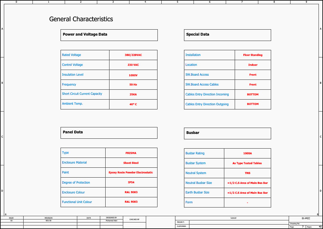
The MCC is housed in a floor-standing Prisma enclosure system, characterized by sheet steel construction with an epoxy resin powder electrostatic paint finish (RAL 9003). The system maintains a degree of protection of IP54, ensuring resilience against dust ingress and splashing water, which is suitable for standard indoor industrial environments.
The general arrangement consists of multiple modular vertical sections:
Incoming & Metering Section (800mm width): This section houses the main 1000A NS frame incoming circuit breaker (Q0) and the primary energy metering equipment.
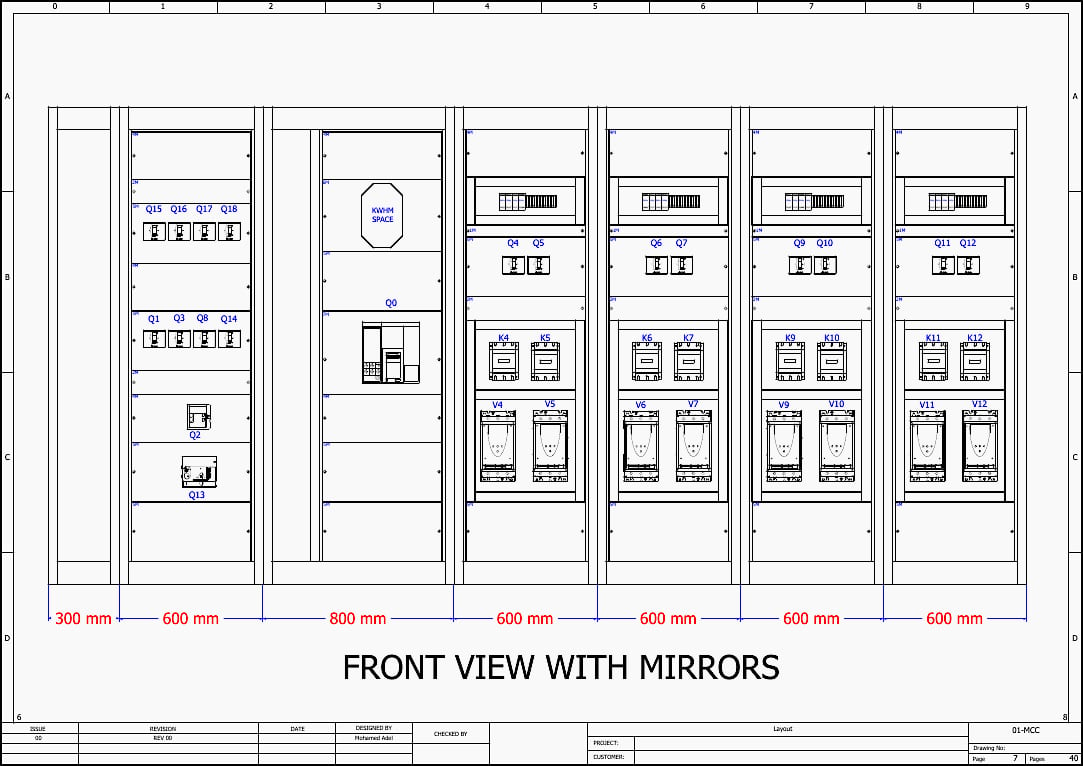
Motor Control Sections (600mm width each): There are multiple 600mm columns dedicated to housing the outgoing circuit breakers and the eight soft starters (V4, V5, V6, V7, V9, V10, V11, V12).
Busbar System: The main busbar is rated for 1000A and is constructed of copper (Cu). The busbar topology utilizes a TNS neutral system, where the neutral busbar size is half the cross-sectional area of the main busbar, and the earth busbar is identically sized to the neutral.
Figure 1 – Front view of the MCC switchgear (without mirrors)
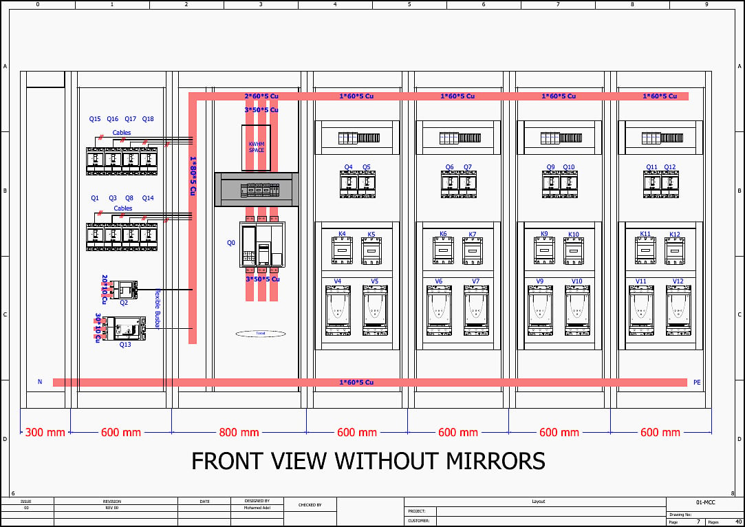
Figure 2 – Front view of the MCC switchgear (with mirrors)
1.2 Electrical Specifications
Let’s break down those electrical specifications from Section 1. In switchgear and MCC design, these four parameters define the fundamental operational boundaries, safety margins, and structural limits of the entire panel.
- Rated Voltage: 380/220 VAC at 50 Hz.
- Control Voltage: 230 VAC.
- Short Circuit Capacity: 25 kA.
- Insulation Level: 1000V.
Here is a deeper look at what each specification means and how it dictates the panel’s design:
1.2.1 Rated Voltage: 380/220VAC at 50 Hz
This is the primary power supply that the MCC will distribute to the external loads (the motors).
380V (Phase-to-Phase): This is the three-phase AC voltage used to drive the heavy industrial loads. The main 1000A copper busbars and the power terminals of all the ATS22 soft starters operate at this voltage.
220V (Phase-to-Neutral): Because the panel utilizes a TNS neutral system, tapping across any single phase (L1, L2, or L3) and the Neutral busbar provides 220V. This is often used for single-phase auxiliary loads.
50 Hz: The standard grid alternating current frequency the equipment is designed to accept. The soft starters rely on this stable frequency to correctly time the firing of their internal thyristors during motor acceleration.
1.2.2 Control Voltage: 230 VAC
While the main busbars carry 380V to do the “heavy lifting,” the control voltage is the electrical supply that powers the panel’s “brain.”
What it powers: This 230V circuit powers the contactor coils (like -K4 through -K12), the auxiliary fault relays (-KF, -KR), the indicator lamps on the panel doors (ON, OFF, TRIP), the power meters, and the cooling fan thermostats.
Why it matters: Separating the control voltage from the main three-phase power increases operator safety and circuit reliability. It means pushbuttons and selector switches only handle lower, safer voltages and currents, rather than directly switching the 380V motor feeds.
Figure 3 – MCC Electrical specifications (click to zoom)
1.2.3 Insulation Level: 1000V
Also known as the Rated Insulation Voltage (Ui), this specifies the dielectric strength of the panel’s internal components.
What it means: It is the maximum voltage that the non-conductive materials in the panel—such as the plastic standoffs holding the copper busbars, the wire jacketing, and the circuit breaker casings—can withstand continuously without breaking down and allowing electricity to arc through them.
Why 1000V for a 380V system? This built-in safety margin ensures the panel can safely handle overvoltage transients, voltage spikes from the grid, and the inductive “kickback” voltage that occurs when large motors are suddenly switched off, preventing dangerous electrical arcing to the grounded metal enclosure.
1.2.4 Short Circuit Current Capacity: 25KA
This is a critical safety and structural rating, often referred to as the short-time withstand current (Icw).
What it means: If a massive short circuit occurs downstream (e.g., a catastrophic motor failure or a severed main cable), fault current will instantly rush through the MCC’s main busbars.
The physical reality: When 25kA flows through parallel copper busbars, it generates immense electro-dynamic magnetic forces that physically try to violently repel or attract the copper bars to one another.
Furthermore, the massive current generates extreme, instantaneous heat. A 25kA rating ensures the busbar supports will not snap, and the copper will not warp or melt under these extreme mechanical and thermal stresses before the protection logic intervenes.
Further Study – Instructions for generating specifications and selecting the main components of an HV substation
Instructions for generating specifications and selecting the main components of an HV substation
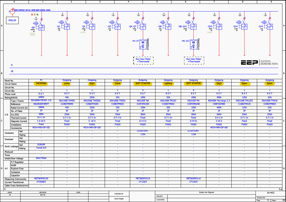
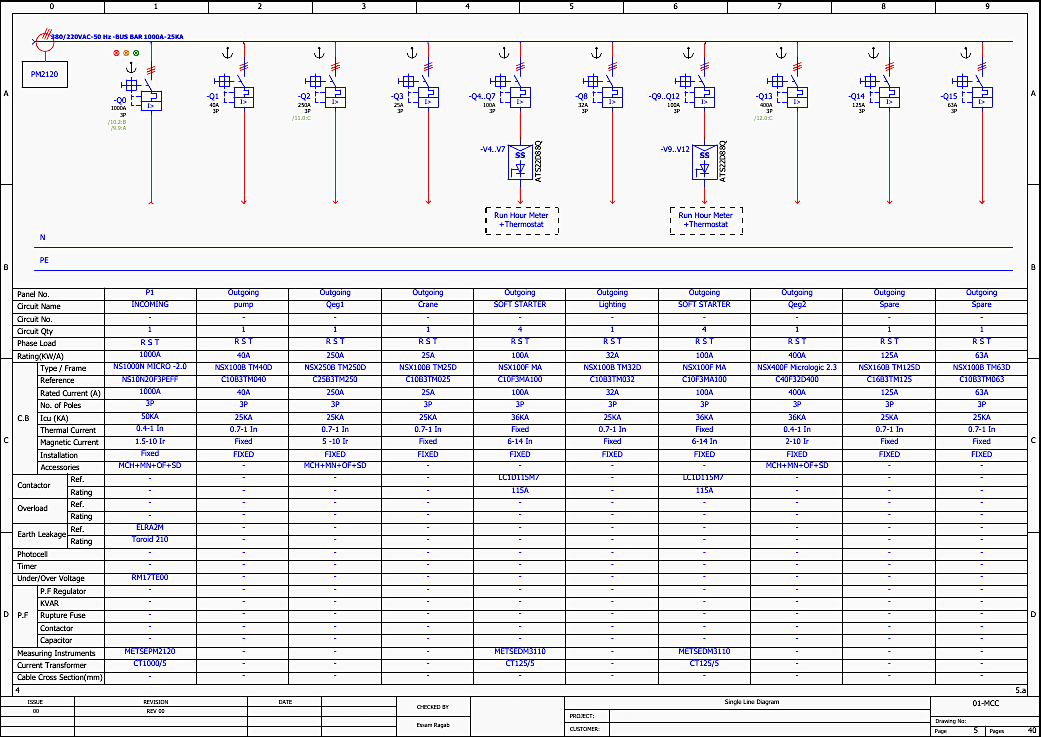
2. Single Line Diagram (SLD) Overview (Pages 5-6)
The SLD dictates the power flow and primary protection hierarchy of the MCC. The 1000A busbar is fed and distributed as follows:
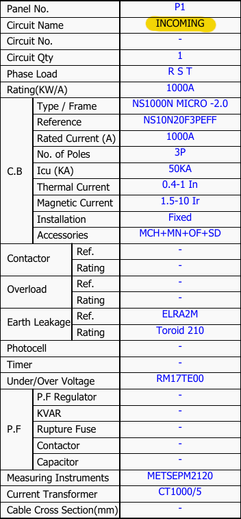
2.1 Main Incomer
Reference: Q0 [Page 5, Grid B-2].
Component: Schneider Electric NS1000N.
Functionality: This is a 1000A, 3-pole circuit breaker equipped with a MicroLogic 2.0 trip unit. The MicroLogic unit provides electronic protection, allowing for precise adjustments of the thermal (Ir) and magnetic (Im) trip thresholds to protect the main busbar against overloads and short circuits.
It has an ultimate breaking capacity (Icu) of 50kA. It is equipped with motor mechanism accessories (MCH, MN, OF, SD) for remote operation and status monitoring.
Figure 4 – Incomer specification
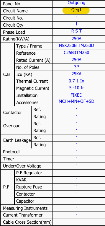
2.2 Outgoing Motorized Feeders
Reference Q2 (250A): [Page 5, Grid B-3] feeds a general outgoing load. It utilizes an NSX250B frame with a TM250D thermal-magnetic trip unit. It includes motor mechanism accessories (MCH, MN, OF, SD).
Reference Q13 (400A): [Page 5, Grid B-8] feeds another heavy outgoing load using an NSX400F frame with a MicroLogic 2.3 electronic trip unit. It also features full motorized accessories.
Figure 5 – Outgoing Motorized Feeder Q2 specs from SLD
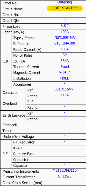
2.3 Soft Starter Feeders (V4-V12)
The panel incorporates eight identical motor control branches. Taking V4 as an example [Page 5, Grid B-5]:
Circuit Breaker (Q4..Q7): 100A NSX100F with a magnetic-only (MA) trip unit (6-14 In adjustable). Magnetic-only breakers are specifically designed for motor protection, providing short-circuit protection while allowing the soft starter and its associated thermal overload relay to handle operational overloads.
Soft Starter: ATS22D88Q. Rated for specific motor loads, facilitating smooth acceleration and deceleration to reduce mechanical wear and electrical starting currents.
Figure 6 – Soft Starter Feeders specs from SLD
2.4 Instrumentation
Main Meter (PM2120): Installed at the incomer [Page 5, Grid A-1] using 1000/5A Current Transformers (CTs) to measure overall panel consumption.
Feeder Meters (DM3110): Installed at the soft starter branches using 125/5A CTs for individual motor load monitoring.
Figure 7 – MCC single-line diagram (click to zoom)
3. Incoming Control and Monitoring (Pages 7-8)
3.1 Voltage Monitoring and Power Metering (Page 7)
The control circuit for the main instrumentation ensures accurate logging and grid stability monitoring.
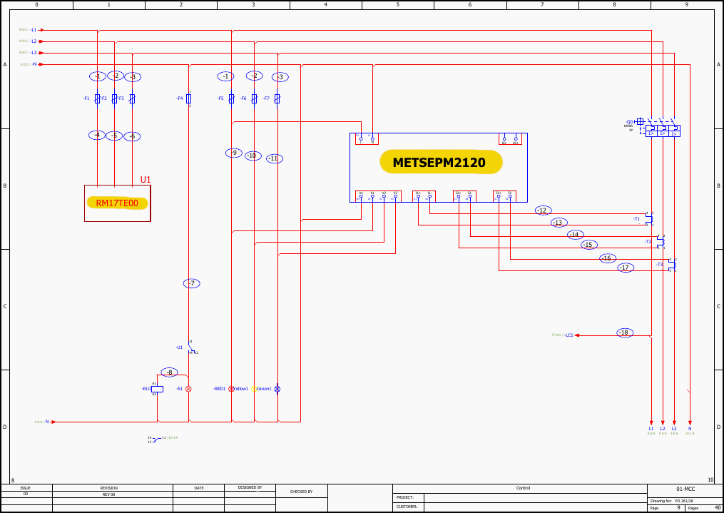
Reference PM2120: [Page 7, Grid B-5]. This is a Schneider Electric PowerLogic meter. It receives its voltage signals directly from the L1, L2, L3, and N phases via protective fuses (-F1, -F2, -F3). It calculates real-time power, energy consumption, and harmonic distortion.
Reference RM17TE00 (U1): [Page 7, Grid B-2]. This is a multifunction control relay that monitors phase sequence, phase loss, overvoltage, and undervoltage. If the grid parameters fall outside the programmed thresholds, the relay’s internal contact (11-14) will change state. This contact is wired in series with the main breaker’s control logic to prevent the system from energizing under unstable grid conditions.
Figure 8 – The control circuit for the main instrumentation: PM2120 and RM17TE00
3.2 Main Breaker (Q0) Control Schematic (Page 8)
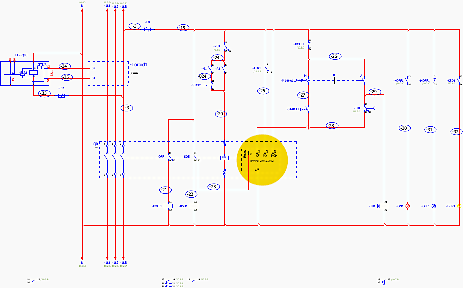
The control logic for the 1000A NS main incomer dictates how the breaker is opened, closed, and tripped [Page 8, Grid C-4].
Motor Mechanism (MCH): [Page 8, Grid C-4]. This internal motor automatically charges the breaker’s closing springs when control voltage (230VAC) is applied. Once charged, the breaker is ready to be closed.
Closing Coil (XF) and Opening Coil (MX): These coils receive electrical pulses from the local START (-S1) and STOP pushbuttons, or from remote commands, causing the breaker to mechanically close or open.
Undervoltage Release (MN): [Page 8, Grid C-3]. This is a critical safety feature. The MN coil must be continuously energized with control voltage to allow the breaker to remain closed.
Earth Leakage Relay (ELR1): [Page 8, Grid B-1 to B-4]. Connected to a Toroid (Current Transformer) that encompasses all three phases and neutral. It measures the vector sum of the currents. Under normal conditions, the sum is zero.
If a ground fault occurs, a residual current flows, which the toroid detects. If this current exceeds the 30mA threshold, the ELR1 relay trips, breaking the control circuit to the MN coil and tripping Q0.
Figure 9 – Control logic for the 1000A NS main incomer (click to zoom)
4. Outgoing Motorized Feeder Control (Pages 9-10)
The outgoing motorized breakers (Q2 and Q13) share a similar control philosophy to the main incomer, tailored for distribution rather than main intake.
4.1 Q2 Control Logic (Page 9)
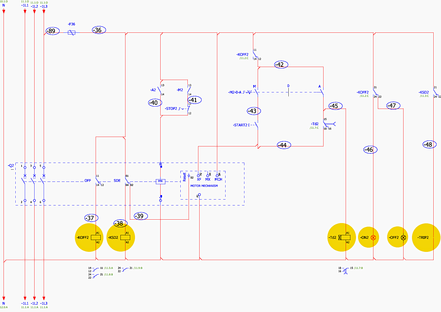
Reference Q2 Motor Mechanism: [Page 9, Grid C-4]. The 250A NSX breaker is equipped with a front-mounted motor mechanism.
Control Relays (-KOFF2, -KSD2, -Td2): [Page 9, Grid D-2 to D-7]. These auxiliary relays manage the logic states.
- -KOFF2 indicates the breaker is open.
- -KSD2 interfaces with the SDE (Fault-trip indication) contact. If the breaker trips due to an overload or short circuit (as opposed to a manual open command), the SDE contact closes, energizing -KSD2. This illuminates the -TRIP2 indicator lamp and blocks automatic reclosing until a manual reset is performed.
- -Td2 is a time-delay relay, ensuring that the motor mechanism has sufficient time to complete its internal spring-charging cycle before allowing a subsequent close command.
Local Indication: Lamps are provided for ON (-ON2) , OFF (-OFF2) , and TRIP (-TRIP2), providing the operator with immediate visual status of the 250A feeder.
Figure 10 – Outgoing Q2 motorized feeder control circuit (click to zoom)
5. Soft Starter Control Topologies (Pages 11-34)
The MCC contains eight identical soft starter circuits (V4, V5, V6, V7, V9, V10, V11, V12). The design utilizes the Schneider Electric Altistart ATS22D88Q. To thoroughly explain this, we will analyze the template using Soft Starter V4 (Pages 11-13) and Soft Starter V12 (Pages 32-34) as representative examples.
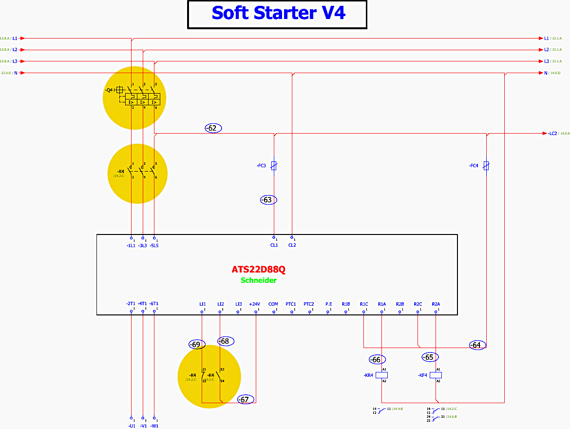
5.1 Power Circuit and Bypass Logic
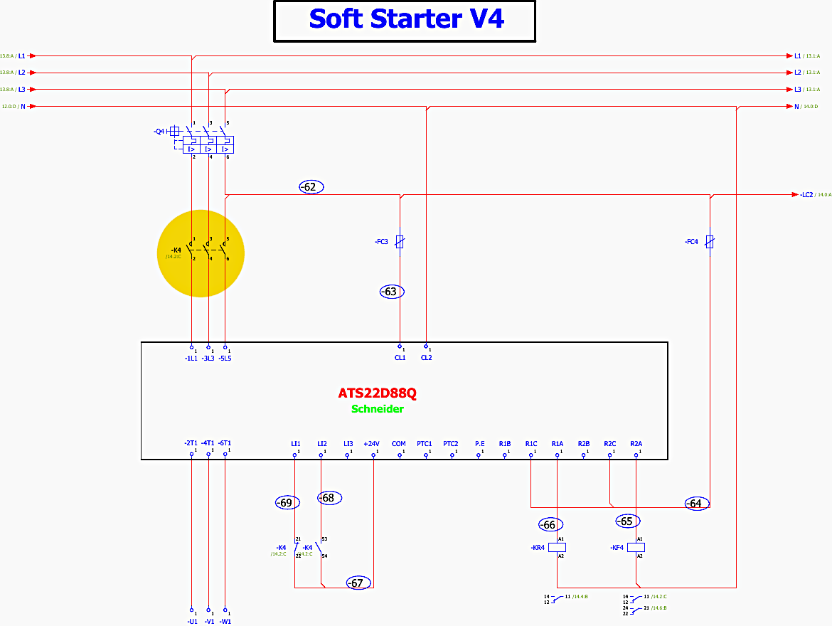
Reference Soft Starter ATS22D88Q: [Page 11, Grid C-4]. The ATS22 controls the voltage applied to the motor during startup using anti-parallel thyristors on all three phases. By gradually increasing the thyristor firing angle, it ramps up the voltage, controlling the motor’s starting current and torque.
Main Contactor (-K4): [Page 11, Grid B-2]. This contactor is located upstream of the soft starter. It must close to provide 380V power to the ATS22 power terminals (1L1, 3L2, 5L3).
Bypass Operation: The ATS22 includes internal bypass contacts. Once the soft starter has successfully ramped the motor up to full nominal speed, it internally closes its bypass contacts. This shunts the power away from the thyristors, routing it directly through solid copper connections.
This drastically reduces heat dissipation inside the panel during continuous run operation.
Figure 11 – Soft starter power circuit and bypass logic (click to zoom)
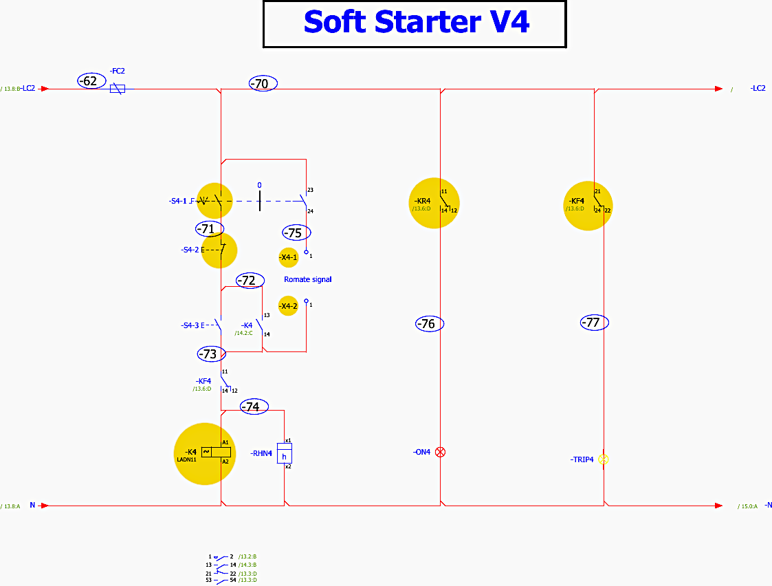
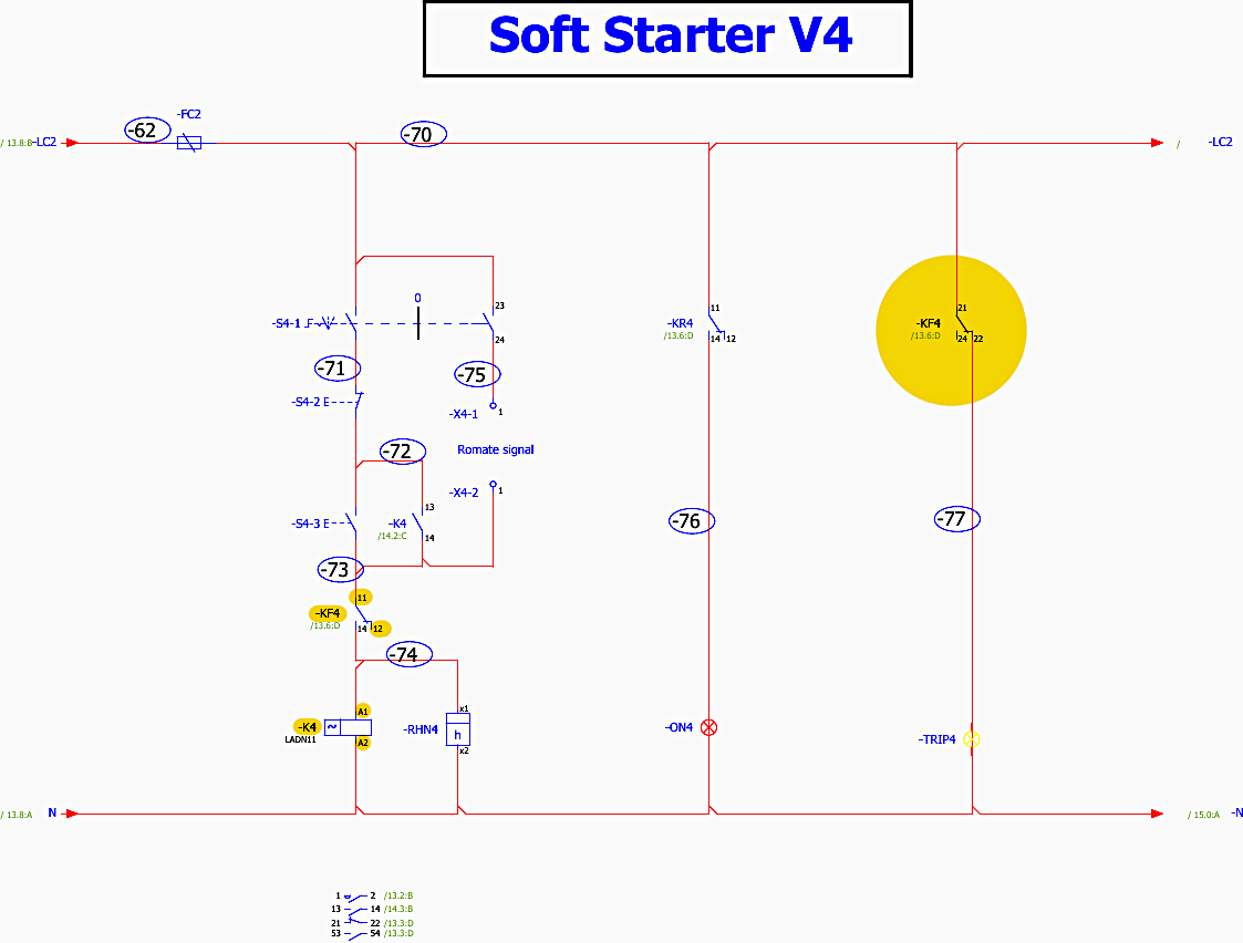
5.2 Soft Starter Control Logic (Page 12)
The control schematic for the soft starter governs the sequence of operations required to safely start and stop the motor.
Start/Stop Circuit: [Page 12, Grid B-1]. The circuit utilizes standard local pushbuttons (-S4-1 for STOP, -S4-2 for START) alongside remote signal contacts (-X4-1, -X4-2).
Start Sequence:
- When a START command is issued, the auxiliary relay -KR4 is energized [Page 12, Grid C-2].
- This initiates the closing of the main upstream line contactor -K4 [Page 12, Grid C-3].
- Once -K4 is closed, power is available at the soft starter. A run command is simultaneously sent to the ATS22 logic inputs.
- The soft starter begins its programmable voltage ramp to accelerate the motor.
Fault Logic: The ATS22 monitors for various motor faults (phase loss, locked rotor, thermal overload). If a fault is detected, the soft starter’s internal fault relay changes state. This signal is sent to the -KF4 fault relay in the panel [Page 12, Grid C-5]. Energizing -KF4 breaks the control circuit to -K4, instantly dropping the line contactor and removing power from the motor, whilst simultaneously illuminating the -TRIP4 lamp.
Figure 12 – Control schematic for the soft starter (click to zoom)
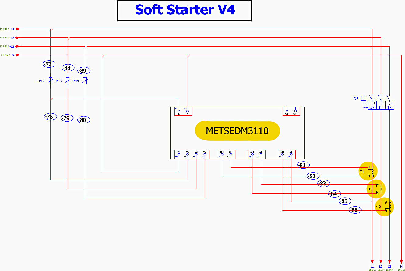
5.3 Feeder Metering Integration (Page 13)
Each motor branch is monitored by a dedicated power meter.
Reference METSEDM3110: [Page 13, Grid B-5]. This meter measures the specific power consumption of the V4 motor branch.
Current Transformers (-T4, -T5, -T6): [Page 13, Grid C-8]. Three CTs step down the high motor current to a manageable 5A signal for the DM3110 meter. These are wired to the meter’s current input terminals (I1, I2, I3). The CTs allow operators to monitor phase balance and actual running current, which is critical for predictive maintenance of the mechanical loads (such as the connected pumps and cranes).
The logic detailed for V4 is perfectly mirrored across V5 through V12. For example, Soft Starter V12 [Pages 32-34] utilizes the identical ATS22D88Q , controlled by line contactor -K12 , with start/stop logic governed by -KR12 and -KF12 , and metered by its own DM3110 utilizing CTs -T25, -T26, and -T27.
Figure 13 – Each motor branch is monitored by a dedicated power meter METSEDM3110 (click to zoom)
6. Auxiliary Circuits and Thermal Management (Pages 35-36)
Because this MCC houses eight ATS22 soft starters and multiple heavy-duty circuit breakers, the internal heat dissipation (I²R losses) will be significant. The Prisma IP54 enclosure restricts natural airflow, necessitating active forced-air cooling.
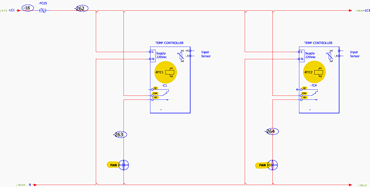
6.1 Thermostat Control Logic
Reference RTC1 & RTC2: [Page 35, Grid B-2 and C-2]. These are temperature controllers (thermostats) mounted within the panel. They are supplied with 220VAC control power.
Operation: The thermostats utilize an input sensor to monitor the ambient internal temperature of the MCC.
Cooling Fans: [Page 35, Grid C-8]. If the internal temperature rises above the setpoint (typically configured between 35°C and 45°C), the thermostat’s internal relay contact (NO/COM) closes. This energizes the roof-mounted cooling fans (“TOP FAN” indicated in the general layouts ).
Page 36 details the continuation of this thermal management, showing duplicate controllers (-RTC3, -RTC4) controlling additional fan banks (-266, -267), ensuring redundancy and adequate airflow across all 600mm vertical sections of the MCC.
Figure 14 – Thermostat Control Logic (click to zoom)
7. Conclusion
The 1000A Prisma M Low Voltage MCC is a highly engineered, robust distribution and control node. By utilizing motorized NS and NSX frame circuit breakers alongside ATS22 soft starters, it provides remote operability and superior mechanical protection for the attached motor loads.
The comprehensive use of PowerLogic (PM2120 and DM3110) metering at both the incomer and feeder levels ensures that operators have total visibility over energy consumption, phase balance, and system health.
The integrated thermal management guarantees that despite the high IP54 rating and significant internal power electronics, the system will operate reliably under sustained loads.
8. A Detailed Fault Scenario
(How the protection and control logic work)
Here is a detailed fault scenario based on the schematics provided for the 1000A MCC.
To demonstrate how the protection and control logic interact, we will trace a Motor Thermal Overload Fault occurring on the Soft Starter V4 (Pump) branch.
8.1 The Fault Scenario: Mechanical Jam on Pump V4
Imagine the pump connected to Feeder V4 ingests debris, causing a mechanical jam. The motor is still receiving power but cannot turn (a “locked rotor” condition). This causes the motor to draw an abnormally high current—typically 6 to 8 times its nominal running current.
Here is the exact step-by-step sequence of how the MCC panel detects, isolates, and reports this fault based on your schematics.
Step 1 – Fault Detection by the Soft Starter
Normal State: Prior to the jam, the motor was running normally. The upstream manual circuit breaker -Q4 is closed, the main line contactor -K4 is energized and closed, and the ATS22D88Q soft starter is bypassed.
Detection: As the motor draws locked-rotor current, the ATS22D88Q soft starter begins accumulating thermal energy (I2t) data in its internal electronic protection module.
Because this is an overload (not a dead short circuit), the current does not exceed the magnetic tripping threshold (6-14×In) of the upstream -Q4 (NSX100F MA) circuit breaker. The soft starter is allowed to handle the fault.
Location: Page 11, Grid C-4.
Figure 15 – Step 1: Fault Detection by the Soft Starter (click to zoom)
Step 2 – Tripping the Fault Relay
Action: Once the thermal threshold of the ATS22 is breached, the soft starter initiates an internal trip.
Relay Change: The soft starter’s internal fault relay contacts change state. Specifically, the circuit spanning terminals R2A and R2C.
Panel Hardware: This internal action immediately toggles the external fault auxiliary relay -KF4 located inside the MCC control section.
Location: Page 11, Grid D-7.
Step 3 – Severing the Control Circuit
Action: The actuation of the -KF4 auxiliary relay translates the soft starter’s digital fault into physical control logic.
Breaking the Latch: A normally closed (NC) contact of -KF4 (terminals 11-12) is wired in series with the start/stop latching circuit for the main contactor.
When -KF4 actuates, this contact opens, instantly breaking the 230VAC control voltage to the A1 / A2 coil of the line contactor -K4.
Location: Page 12, Grid B-3.
Figure 16 – Step 3: Severing the Control Circuit (click to zoom)
Step 4 – Physical Power Isolation
Action: With its coil de-energized, the main line contactor -K4 physically drops out (opens).
Result: This severs the 380V power supply at terminals 1L1, 3L3, 5L5, completely isolating the ATS22 soft starter and the jammed motor from the main busbar. The motor is now safe from thermal destruction.
Location: Page 11, Grid B-2.
Step 5 – Operator Feedback and Lockout
Indication: Simultaneously, a normally open (NO) contact on the -KF4 relay (terminals 21-22 or 21-24) closes. This routes control voltage to the -TRIP4 indicator lamp on the front door of the panel, illuminating it to notify the operator of a fault.
The -ON4 run lamp drops out as the contactor opens.
Lockout: If an operator attempts to press the local START button -S4-2, the system will ignore the command. The open -KF4 contact in the control line prevents the -K4 contactor from energizing. The system is locked out until an engineer physically inspects the pump, allows the ATS22 to cool down, and performs a manual reset on the soft starter’s HMI.
Location: Page 12, Grid C-4.
9. Attachment (PDF): Technical Specifications & Drawings For 132 kV Outdoor Gas Insulated Substations & Ancillary Equipment
Download: Technical Specifications & Drawings For 132 kV Outdoor Gas Insulated Substations & Ancillary Equipment (for premium members only):
Related electrical guides & articles


Edvard Csanyi
Hi, I'm an electrical engineer, programmer and founder of EEP - Electrical Engineering Portal. I worked twelve years at Schneider Electric in the position of technical support for low- and medium-voltage projects and the design of busbar trunking systems.I'm highly specialized in the design of LV/MV switchgear and low-voltage, high-power busbar trunking (<6300A) in substations, commercial buildings and industry facilities. I'm also a professional in AutoCAD programming.
Profile: Edvard Csanyi

I am very grateful for coming across this schematic ATS design, especially the very pecice to points detailed schematic design, easy to read and understand, powerful solutions for three in one against the normal 3 in one. As a certified electrician, I managed to invest in a multi-source one. That is PLC, Generator, Solar, wind power and other incoming alternative power supplies. My system works with three-phase and single-phase in that, when either of the 3 single PLC main grid power supplies is off, the available prioritised one will pick up simultaneously; and when all the PLC phases are off, the alternative solar power will take charge, followed by wind turbine power supply and finally the generator. The reason why the generator becomes the final option is because of economic fuel consumption. You can help me market the idea or incorporate me to provide a solution to in case you need it
Hello,
May i ask when the course- ETAP dynamic and static motor starting , available for enrolment?
Regards
John