
Estimated Study Time: 27 minutes
Electrical Schematic Design
Welcome to this comprehensive technical article that delves into the intricacies of electrical schematics, shedding light on crucial elements such as loops, wire connections, auxiliary contacts, MCBs, contactors, circuit breakers, isolators, earth switches, and terminal blocks. In the world of electrical engineering, understanding the design and representation of these components is paramount for ensuring the seamless functioning of systems.
 Fundamental concepts of schematic drawings: Going deeper into analysis and design intricacies
This article aims to provide insights into the designation of loops in schematics, the rationale behind in and out wire connections, the role of auxiliary contacts, the normal position of MCBs, the representation of contactors and auxiliary relays, circuit breaker notation, and the schematic depiction of isolators, earth switches, and terminal blocks.
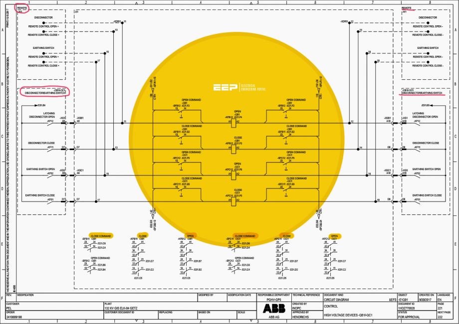
Also, don’t forget to download a complete 132kV GIS Control Cubicle Drawing (PDF, 150 pages), at the end of this article.
Join us on this exploration as we unravel the intricacies of electrical schematic design and enhance our comprehension of these fundamental components in electrical systems.
- Loops and Designation of Loops In the Schematics
- Why wires are connected in the panel at in and out basis and loops are formed
- Auxiliary Contacts and Their Role in Drawings: Understanding the function of auxiliary contacts
- What is the MCB Normal Position, How MCBs are Shown in Schematics
- How Contactors / Auxiliary Relays are shown in schematics and what is Normal position of contactors
- Circuit Breaker Representation in Schematics
- Understanding the Schematic Representation of Isolators in Electrical Systems
- Earth Switch and Representation in Schematics
- Terminal Block in Schematics
- Current Transformer Terminal Blocks
- BONUS! Download complete 132kV GIS Control Cubicle Drawing (PDF, 150 pages)
1. Loops and Designation of Loops in the Schematics
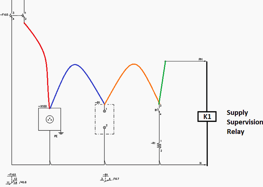
Schematics is designed with designated loops, these are the output of AC or DC MCB providing the supply to the circuit. Whenever, MCB is connected to supply new loop is formed. It is required to give each loop a unique name, Refer to Figure 3, and please check the loop names. Mentioned you can track the loop that is extended to several pages.
It is required to monitor the supply of each loop, therefore at the end of each loop supply supervision relay is installed that is basically attracted armature type relay and that picks up when supply is available and drops. off when supply is failed.
2. Why wires are connected in the panel at in and out basis and loops are formed
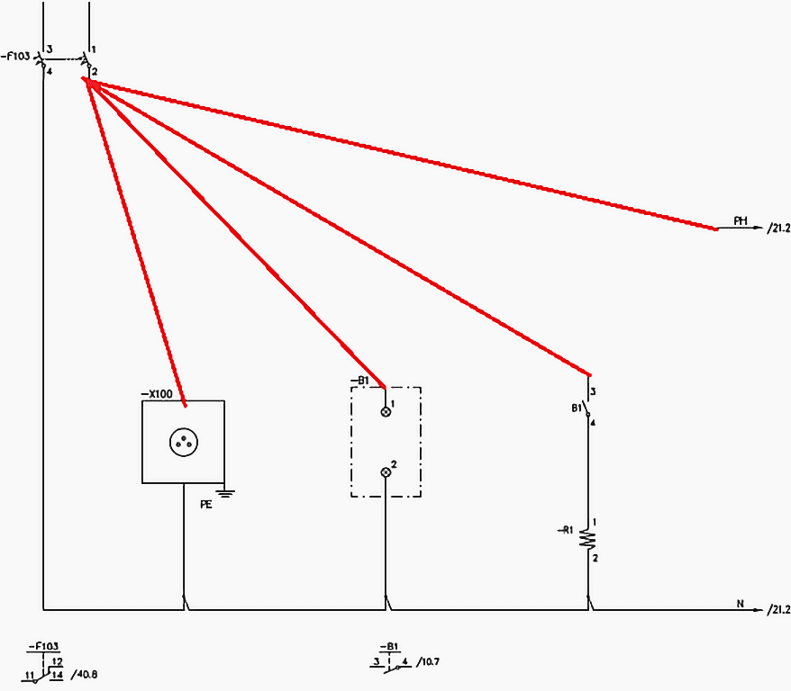
Upon reviewing the panel schematics, we want to understand the rationale of connecting components in a serial loop rather than directly connecting each component to the source terminals. Consult Figure 1, which depicts a non-conventional wiring system that is not commonly utilized due to its numerous inherent problems, which we shall presently examine.
Please check device F103, which is an AC supply MCB. Terminal number 2 of this device is connected to four other devices, requiring four wires to be connected to this terminal. This approach necessitates connecting one wire per device, thereby imposing a limitation on the use of this type of connection.
In addition, there is a bunch of wires gathered at the MCB terminal. It is advised to limit the number of wires in a terminal to a maximum of two in the panel wiring.
Figure 1 – Wrong way of connecting the devices in the panel
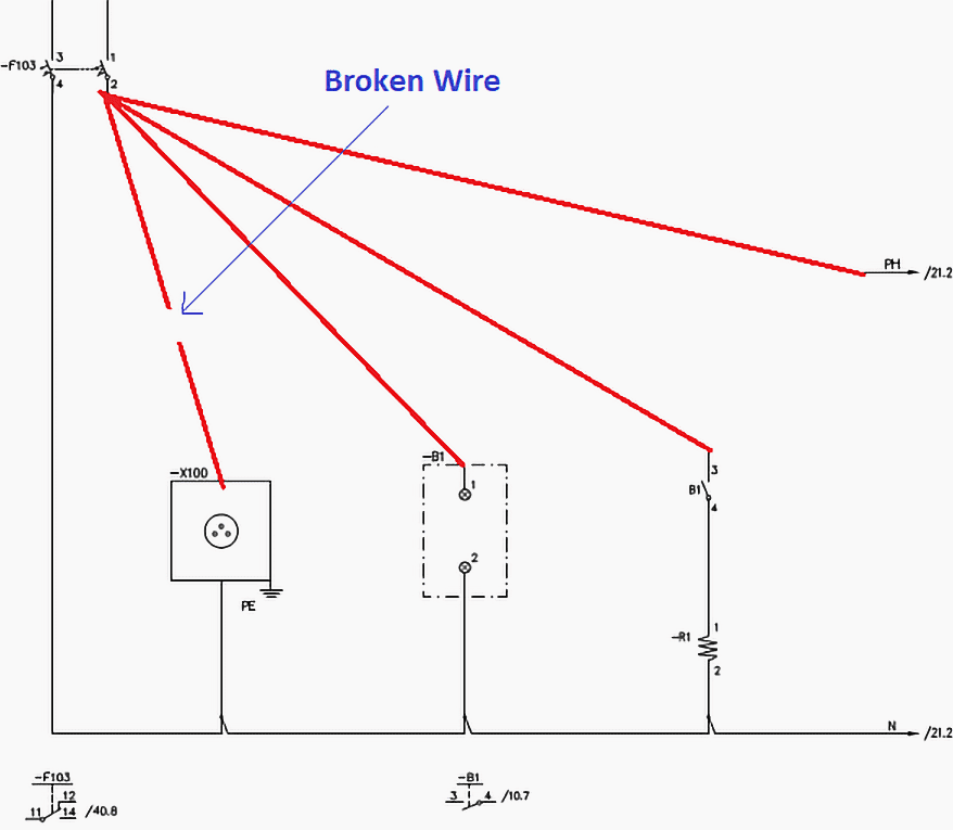
Another concern we would want to address is the condition of the wires and connections within the panels. It is necessary to build a wiring system that ensures the continuous monitoring of all the crucial circuits.
Consult Figure 2, which illustrates that the wire connected to AC socket X100 is severed, resulting in the absence of a means to verify the wire’s condition.
When such a discontinuity occurs, the supervision relay resets and its Normally Close Contact is utilized to indicate the presence of AC loop supply super supervision.
Figure 2 – Unmonitored breakage in the wire
Please refer to Figure 3 showing looping in schematics. All the important loops in the control and protection panels should be monitored. Good examples are trip circuits and control circuits.
Figure 3 – Representation of loop wiring and relay installed at the end of the loop to monitor the healthiness of circuit
3. Auxiliary Contacts and Their Role in Drawings
Understanding the function of auxiliary contacts:
In the realm of electrical systems, each circuit breaker, isolator, or auxiliary relay, such as the Miniature Circuit Breaker (MCB), comes equipped with auxiliary contacts. These auxiliary contacts play a pivotal role in establishing control, signaling alarms, providing indications, and facilitating interlocking mechanisms.
Thus, it becomes imperative to comprehend this fundamental concept.
For a more tangible understanding, let’s delve into the example of an MCB, a device that operates in two primary positions: open or closed. The mechanical connection with the MCB activates two contacts, each serving a distinct purpose. One of these contacts assumes an open state when the MCB is in an open position and closes when the MCB is in a closed position.
Related electrical guides & articles


Muhammad Kashif
Muhammad Kashif Shamshad is an Electrical Engineer and has more than 17 years of experience in operation & maintenance, erection, testing project management, consultancy, supervision, and commissioning of Power Plant, GIS, and AIS high voltage substations ranging up to 500 kV HVAC & ±660kV HVDC more than ten years experience is with Siemens Saudi Arabia.Profile: Muhammad Kashif
