


Estimated Study Time: 41 minutes
Handling Complex GIS Schematics
This article provides a comprehensive, highly detailed technical explanation of the 132kV Gas Insulated Switchgear (GIS) Local Control Cabinet (LCC) schematics, specifically for the plant designated “132 KV GIS ELK-04 GETZ” and the equipment identified as “CONTROL CUBICLE -E1Q02”.
 A Schematic Walkthrough of a 132kV GIS Local Control Cabinet (Document Included, PDF)
Decoding this complex schematic package is essential for engineers, commissioning technicians, and maintenance personnel required to understand the operational logic, safety interlocking matrices, and fault management frameworks inherent to the switchgear.
The primary objective of the article is to analyze the multi-layered schematic document, translating standardized engineering drafting into explicit operational functions.
This breakdown systematically walks through the engineering references, component functions, and exact locations (by sheet, row, and column) within the schematic package to ensure full traceability and understanding of the LCC’s operational logic.
Here is the download link for the complete PDF document with 132kV GIS schematics (175 pages). Open it up, so you can follow the discussion.
Schematics (PDF, 4.0 MB)
- General Documentation and Naming Conventions
- Project Data and Technical Parameters
- Local Control Cabinet (LCC) Design and Layout
- AC Auxiliary Supply and Distribution
- DC Auxiliary Supply and Distribution
- Motor Voltage Supply and Release Hand Cranks
- Circuit Breaker (-QA1) Control Schematics
- Disconnectors and Earthing Switches Control
- Double Operation Interlocking
- Interlocking Schemes
- Position Indication and Alarms
- Instrument Transformers: Measuring and Protection
- Spare Contacts Overview
- Detailed Bill of Materials
- Terminal and Cable Connection Plans
- Summary
- Attachment (PDF) 🔗 Handbook of Power System Protection Maintenance and Field Operation
1. General Documentation and Naming Conventions
(Sheets 001–024)
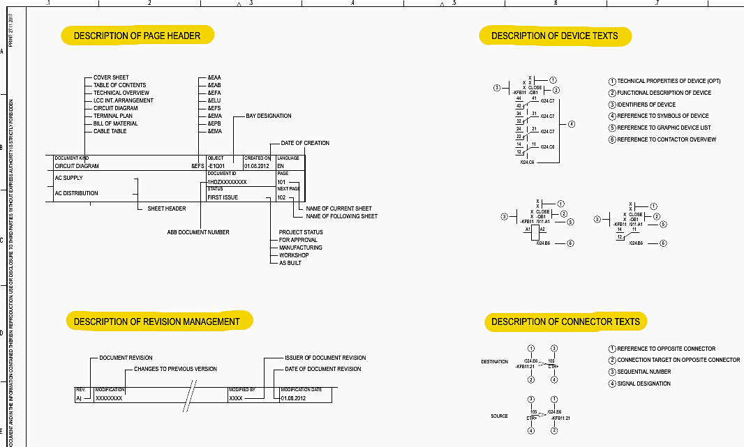
Understanding the standard designations used throughout the schematic is critical for tracing circuits. Sheet 021, Row A, Column 1 details the sheet and terminal designation structure.
Sheet Designations: The 100-series covers AC/DC Supply, the 200-series covers Control and Motors, the 300-series is dedicated to Interlocking, the 500-series manages Indications, the 700-series maps Instrument Transformers, and the 900-series onward handles Bill of Materials, Terminal Plans, and Cables.
Device Identifiers: As shown on Sheet 022, Row B, Column 1, devices are labeled with specific tags (e.g., -KFB11-QB1), where `-K` indicates a relay or contactor, and `-QB1` points to the specific high-voltage disconnector.
Cable Designations: On Sheet 023, Row A, Column 1, the cable numbering logic is established.
64-Pole Plug Connectors: Sheet 024, Row B, Column 1 illustrates the heavy-duty 64-pole connectors used to interface the LCC with the primary GIS equipment. Plugs like -XGA01 and -XGA02 interface with the circuit breaker, while -XGB1 interfaces with the disconnector. These physical plugs allow for rapid deployment and testing of the LCC independently of the heavy switchgear.
Figure 1 – Technical documentation and designations in diagram for 132 GIS (Sheet 022)
2. Project Data and Technical Parameters
(Sheets 031–032)
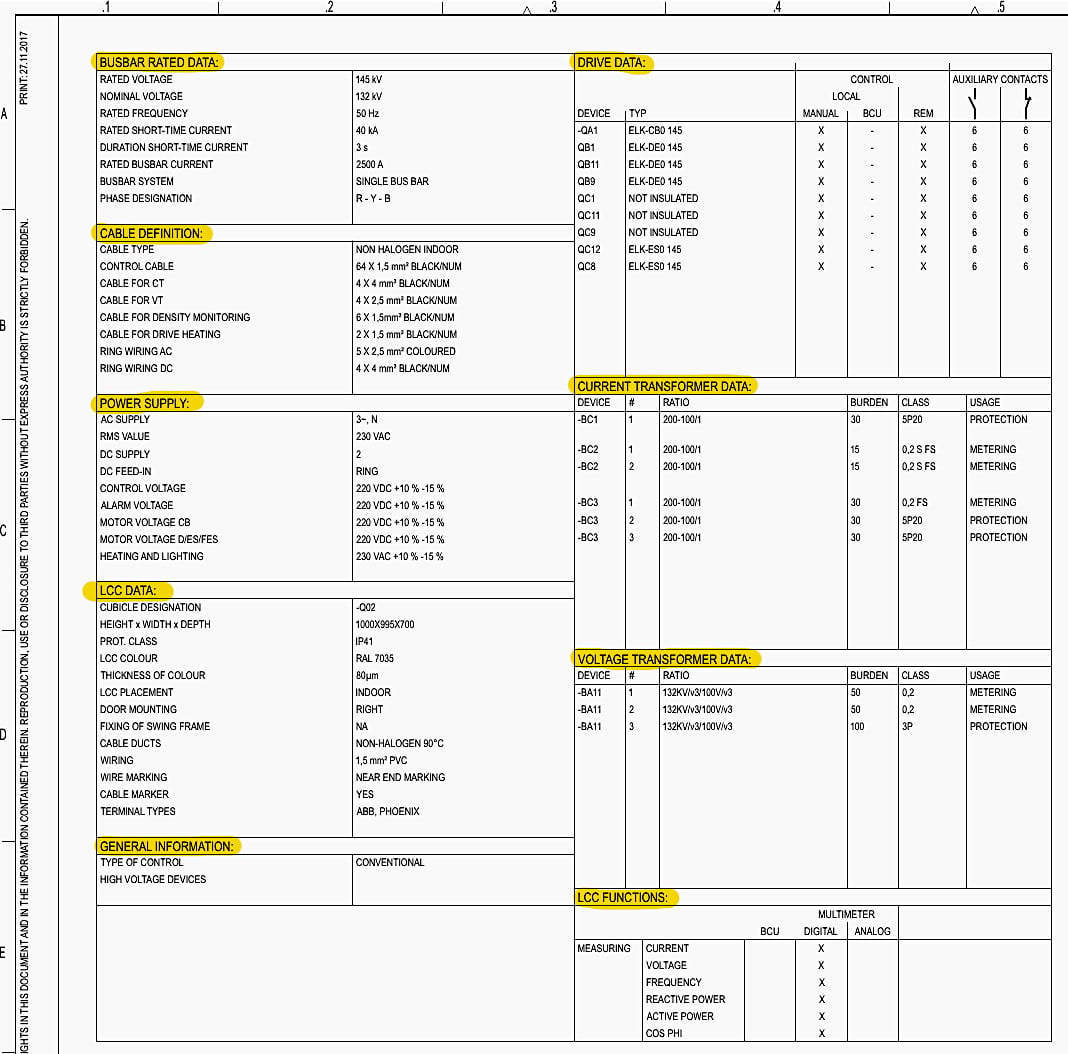
Sheet 031 provides the foundational electrical parameters for the entire bay.
Busbar Rated Data: Located at Sheet 031, Row A, Column 1, the nominal voltage is defined as 132kV, with a maximum rated voltage of 145kV. The system operates at a rated frequency of 50 Hz and is designed to withstand a rated short-time current of 40 kA for 3 seconds.
The primary busbar system is a Single Bus Bar configuration capable of carrying a rated current of 2500 A.
Auxiliary Power Supplies: Sheet 031, Row B, Column 1 specifies the secondary voltages used inside the LCC. The AC supply for heating and lighting is 230 VAC (+10% to -15%). The DC network, which powers critical control, alarms, and motor operations, operates at 220 VDC (-10% to -15%).
Instrument Transformers:
- Current Transformers (CTs): Found on Sheet 031, Row C, Column 3.
CT -BC1 features a ratio of 200-100/1A, a burden of 30VA, and is a 5P20 class core dedicated to protection. CT -BC2 shares the same ratio but is a highly accurate 0.2S FS class core dedicated to metering. CT -BC3 contains both a 0.2 FS metering core and a 5P20 protection core. - Voltage Transformers (VTs): Found on Sheet 031, Row D, Column 3.
The VT -BA11 steps down the primary voltage (132kV/√3) to a secondary voltage (100V/√3). It features two 50VA 0.2 class cores for precision metering and a 100VA 3P class core for protection relays.
Interlocking Logic: Sheet 032, Row B, Column 2 presents the bay interlocking matrix. This mechanical and electrical safety logic prevents operators from performing catastrophic switching sequences.
Furthermore, the table notes that “ALL DISCONNECTORS/EARTHING SWITCHES AND FAST ACTING EARTHING SWITCHES ARE BLOCKED, IF IN ANY DEVICE THE HAND CRANK IS INSERTED”. This ensures that if a human operator is physically cranking a motor drive, the electrical remote control cannot override and injure them.
Figure 2 – 132kV GIS project data and technical parameters
3. Local Control Cabinet (LCC) Design and Layout
(Sheets 041–074)
The physical and ergonomic design of the cabinet is mapped out in the 040 to 070 series of sheets.
Exterior View: Sheet 041, Row B, Column 2 shows the LCC’s outer dimensions. The cabinet stands 1000mm high, 995mm wide, and 700mm deep. It features a right-hinged door with a 170-degree opening angle and is constructed from 2mm Sendzimir zinc-coated steel plate.
Interior Arrangement: Sheet 061 reveals the internal mounting plate layout. Multiple horizontal DIN rails accommodate the dense array of miniature circuit breakers (MCBs), contactors, timers, and heavy-duty terminal blocks (e.g., -XDCT11 for CT connections).
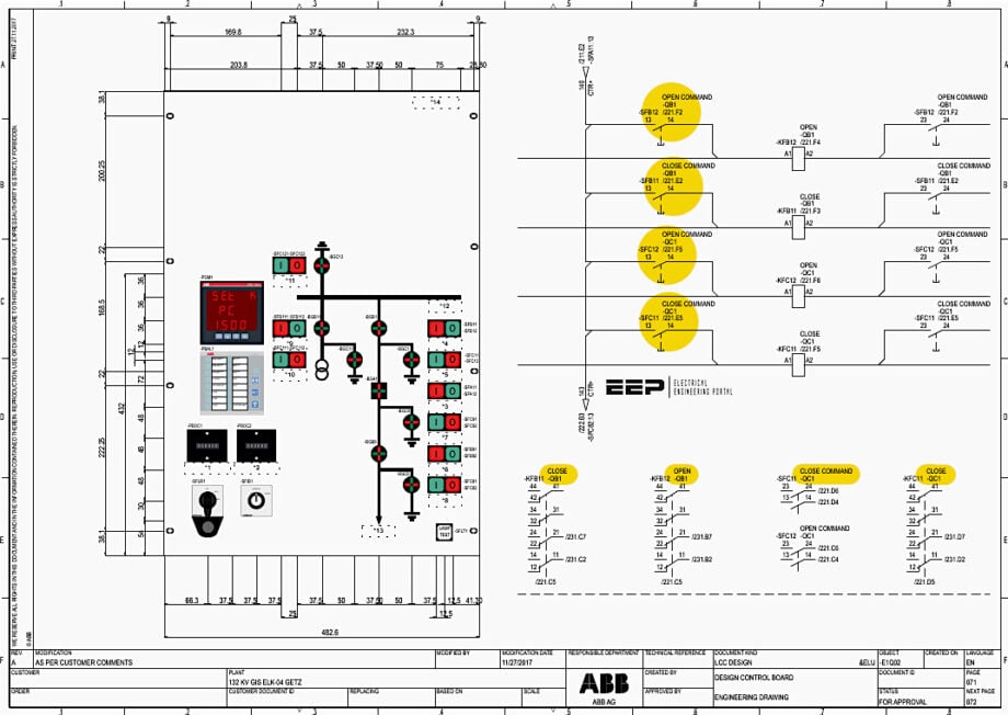
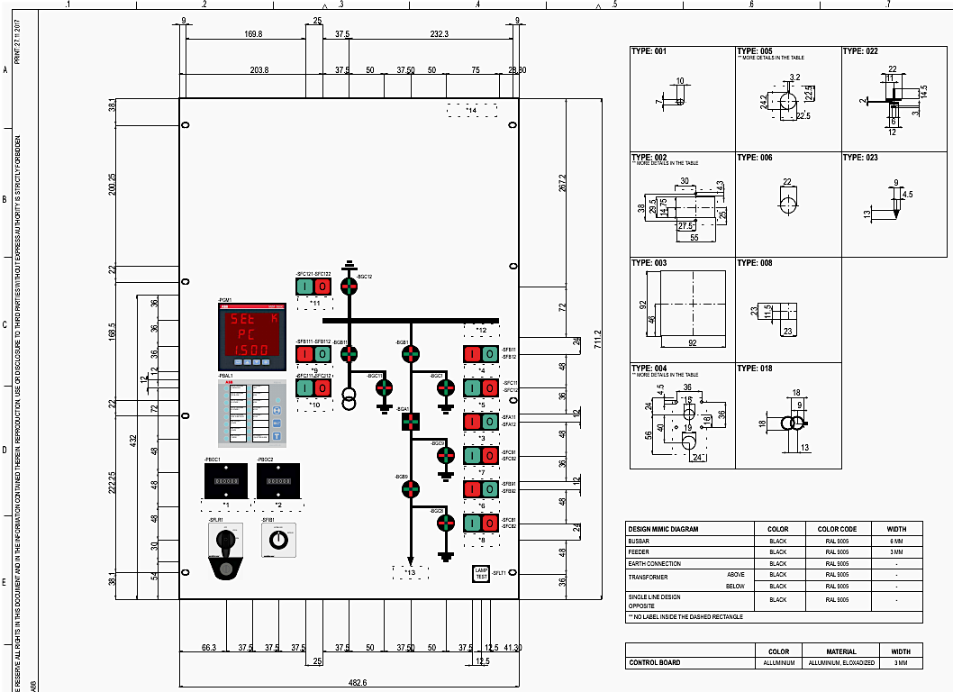
Mimic Diagram: The front control board features a single-line mimic diagram allowing the operator to instantly visualize the status of the switchgear. Sheet 071, Row C, Column 3 details this board. The busbar mimic lines are drawn in black (RAL 9005) with a thickness of 6mm, while the feeder lines are drawn at 3mm.
Positioned along this mimic are LED switch position indicators (e.g., -BGA1 for the circuit breaker, -BGC1 for the earthing switch) that illuminate red or green to show live status.
Control Board Devices: Sheet 074 maps the specific switches on the front panel. Located at Row B, Column 1 is -SFLR1, the Local/Remote selector switch. This key-operated switch (Key Number: CL1) allows control to be transferred from the remote substation control room to the local panel for maintenance.
Next to it is -SFLT1, the Lamp Test push button, which forces all LEDs on the mimic board to illuminate, ensuring no bulbs are burnt out.
Figure 3 – LCC exterior view (Sheet 041)
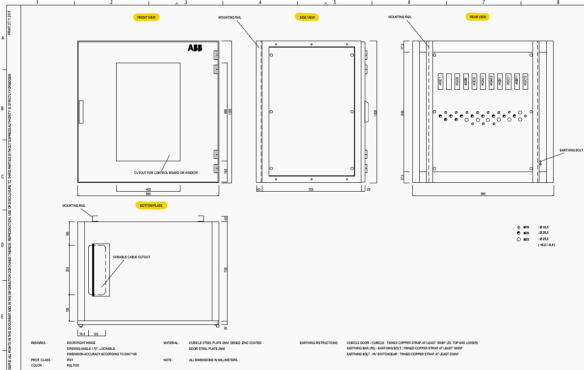
Figure 4 – LCC internal arrangement drawing (Sheet 061)
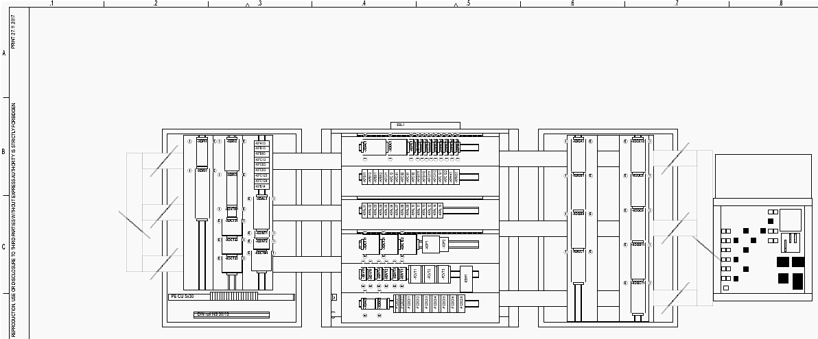
Figure 5 – LCC design control board drawing (Sheet 071)
4. AC Auxiliary Supply and Distribution
(Sheets 101–103)
The AC supply is strictly utilized for non-critical loads such as space heaters and cubicle lighting, as detailed in the 100-series sheets.
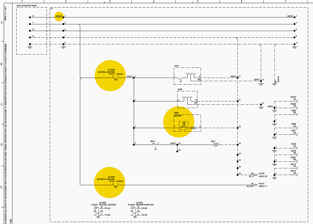
AC Infeed: On Sheet 101, Row A, Column 1, the primary AC/DC auxiliary panel feeds into the LCC at terminal block -XDAC0. The system brings in phases R, Y, B, alongside a Neutral (N) and Protective Earth (PE).
Distribution MCBs: At Sheet 101, Row B, Column 3, the voltage is distributed through two specific miniature circuit breakers. -FCAC01 is a 2-pole MCB designated for the internal LCC heating and lighting. -FCAC02 is dedicated to the external “Heater HV Devices” located inside the actual GIS drives out in the yard.
Cabinet Heating: On Sheet 101, Row C, Column 4, the schematic shows -EBH1, a 50W internal cabinet heater. This prevents condensation from forming on the sensitive protection relays and control boards inside the LCC.
High Voltage Device Heaters: Moving to Sheet 102, the AC power routed through -FCAC02 is distributed to the GIS components. Row A, Column 4 shows the circuit branching out to the Circuit Breaker -QA1 heater.
Row B, Column 4 routes power to the Disconnector/Earthing Switch -QB1/-QC1. Row C and D continue routing AC heating power to -QB9/-QC9 and -QC8 respectively.
Instrument Transformer Heaters: Sheet 103, Row B, Column 4 extends the heating circuits to the Current Transformers -BC1, -BC2, -BC3. Row D, Column 4 shows the heater circuit for the Voltage Transformer -BA11.
Figure 6 – AC auxiliary supply and distribution schematic (Sheet 101)
5. DC Auxiliary Supply and Distribution
(Sheets 151–153)
The 220V DC supply is the lifeblood of the LCC, operating the trip coils, relays, motors, and logic circuits even during a total AC station blackout.
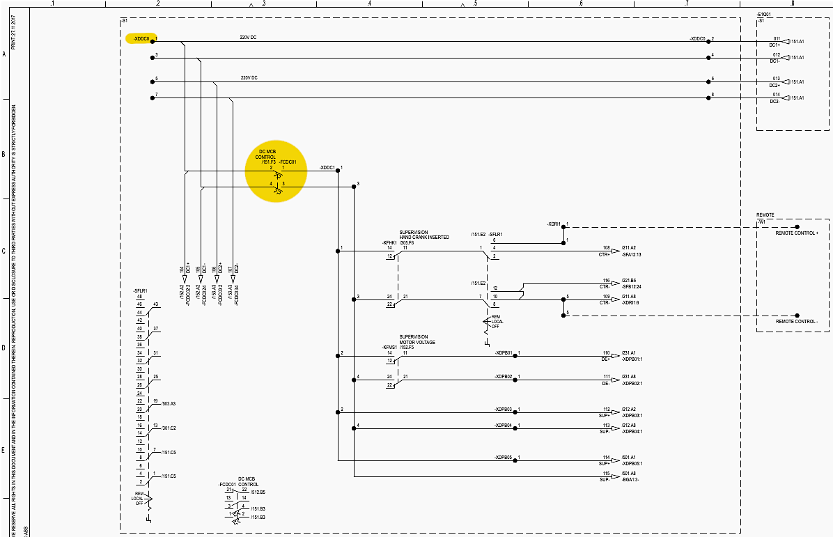
DC Infeed and Source Selection: Sheet 151, Row A, Column 1 shows the incoming 220V DC supply landing on terminal block -XDDC0. This power is immediately routed through the Local/Remote selector switch -SFLR1 at Row B, Column 2, allowing operators to isolate remote control commands for safety during maintenance.
DC Distribution (MCBs): Sheet 151, Row C, Column 3 shows the first critical MCB, -FCDC01, which protects the main “Control” circuitry.
Interlocking and Motor Control: Moving to Sheet 152, the DC bus continues. Row B, Column 3 contains -FCDC02, protecting the “Interlocking” logic circuits. Row C, Column 3 houses -FCDC04, which supplies high-current DC power to the “Motor Control” circuits that physically drive the disconnectors.
Immediately below it at Row D, Column 3 is -FCDC05, dedicated to the Circuit Breaker’s “Hydraulic Pump” motor.
Trip Coil Redundancy: High voltage circuit breakers always feature redundant trip coils to guarantee the breaker opens during a fault. Sheet 152, Row D, Column 3 features -FCDC08, an MCB dedicated solely to “Trip 1”. Sheet 153, Row C, Column 3 features -FCDC06, a completely isolated MCB for “Trip 2”.
Indication Supply: Sheet 153, Row C, Column 3 also houses -FCDC03, which protects the “Indication” circuits. This powers the mimic board LEDs and alarm annunciators.
Figure 7 – DC auxiliary supply and distribution schematic (Sheet 151)
6. Motor Voltage Supply and Release Hand Cranks
(Sheets 201–205)
The 200-series begins by detailing the motor voltage routing and the critical safety interlocks involving manual hand cranks.
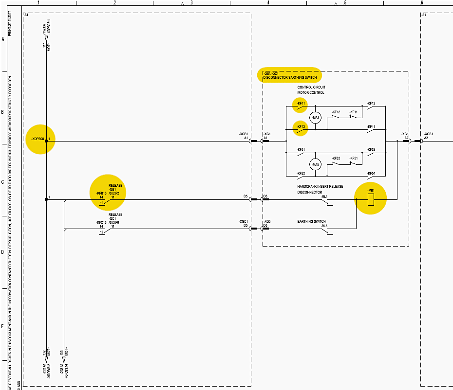
-QB1 / -QC1 Motor Supply: Sheet 201, Row A, Column 1 shows the incoming DC motor power from the potential busbar -XDPB08.
Hand Crank Release Safety: At Sheet 201, Row B, Column 4, the schematic details the “Handcrank Insert Release” circuit for -QB1. When an operator inserts a physical hand crank into the disconnector drive mechanism to operate it manually, a limit switch -MB1 is physically depressed. This actuates relay -KF11 and -KF12 (Row B, Col 4), which electrically disconnects the DC supply from the motor.
Replication Across Devices: This exact safety logic is replicated for every motorized switch in the bay. Sheet 202 details the motor supply and hand crank interlock for the Fast Acting Earthing Switch -QC8 (Row C, Col 4). Sheet 203 covers the -QB9/-QC9 disconnector/earthing switch combination (Row B, Col 4).
Sheet 204 handles the -QB11/-QC11 combination (Row B, Col 4). Finally, Sheet 205 protects the -QC12 maintenance earthing switch (Row C, Col 4).
Figure 8 – Motor voltage supply circuit diagram (Sheet 201)
7. Circuit Breaker (-QA1) Control Schematics
(Sheets 211–214)
The control logic for the primary 132kV Circuit Breaker -QA1 is highly complex, featuring anti-pumping logic, dual tripping, and SF6 gas blocking.
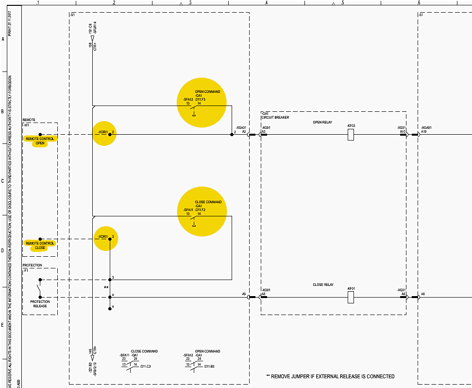
Command Routing: Sheet 211 maps the initial command inputs. Row B, Column 4 illustrates the “Open Command” circuit. An open command can originate from the remote interface (-XDRI1, Row B, Col 2) or the local push button (-SFA12, Row B, Col 3).
This triggers the “Open Relay” -KF02 at Row B, Column 5. Similarly, Row C, Column 4 details the “Close Command”, routed through the local close push button -SFA11 to the “Close Relay” -KF01.
Figure 9 – Circuit Breaker (-QA1) Control Schematics (Sheet 211)
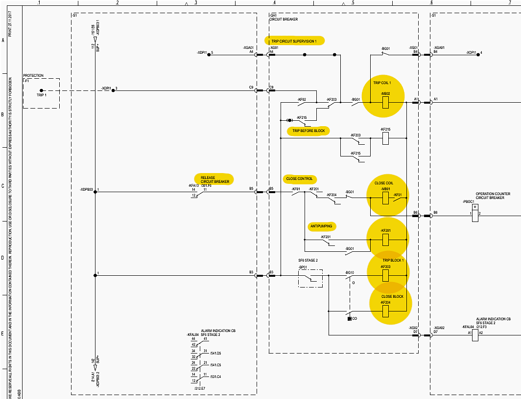
Primary Trip Circuit (Trip 1): Sheet 212 documents the execution of the open command. Row A, Column 4 highlights “Trip Circuit Supervision 1“. This is a continuous trickle current that monitors the health of the trip coil wire; if the wire breaks, an alarm is instantly raised because the breaker can no longer protect the grid.
At Row B, Column 6, the actual “Trip Coil 1” -MB02 is shown. It is energized when the -KF02 open relay closes its contacts.
Closing Circuit and Anti-Pumping: On Sheet 212, Row C, Column 6 sits the “Close Coil” -MB01. Before a close command can reach this coil, it must pass through the Anti-Pumping relay -KF201 at Row D, Column 5. If a close command is continuously held down while a fault exists (causing the protection relay to instantly trip the breaker), the anti-pumping relay locks out the close circuit.
Gas Density Blocking: GIS equipment relies on pressurized SF6 gas to quench electrical arcs. If gas pressure drops, operating the breaker will cause a catastrophic explosion. Sheet 212, Row D, Column 5 details the “Trip Block 1” -KF203 and “Close Block” -KF204 logic.
These relays are controlled by the -BP01 SF6 density monitor. If SF6 Stage 2 (low pressure) is reached, -KF204 electrically severs the closing and tripping paths, locking the breaker in its current state.
Secondary Trip Circuit (Trip 2): Sheet 213 mirrors the trip logic of Sheet 212 but utilizes a completely separate DC supply and Trip Coil 2 (-MB03, Row B, Col 6) for 100% redundancy.
Hydraulic Pump Control: The breaker uses hydraulic pressure to forcefully snap the contacts open or closed. Sheet 214 details the “Hydraulic Pump” -MA1 at Row C, Column 5. The motor is controlled by contactors -KF208 and -KF210 (Row B, Col 5), which monitor the hydraulic accumulator pressure and automatically cycle the pump to maintain operational readiness.
Figure 10 – Closing circuit and anti-pumping schematic
8. Disconnectors and Earthing Switches Control
(Sheets 221–225)
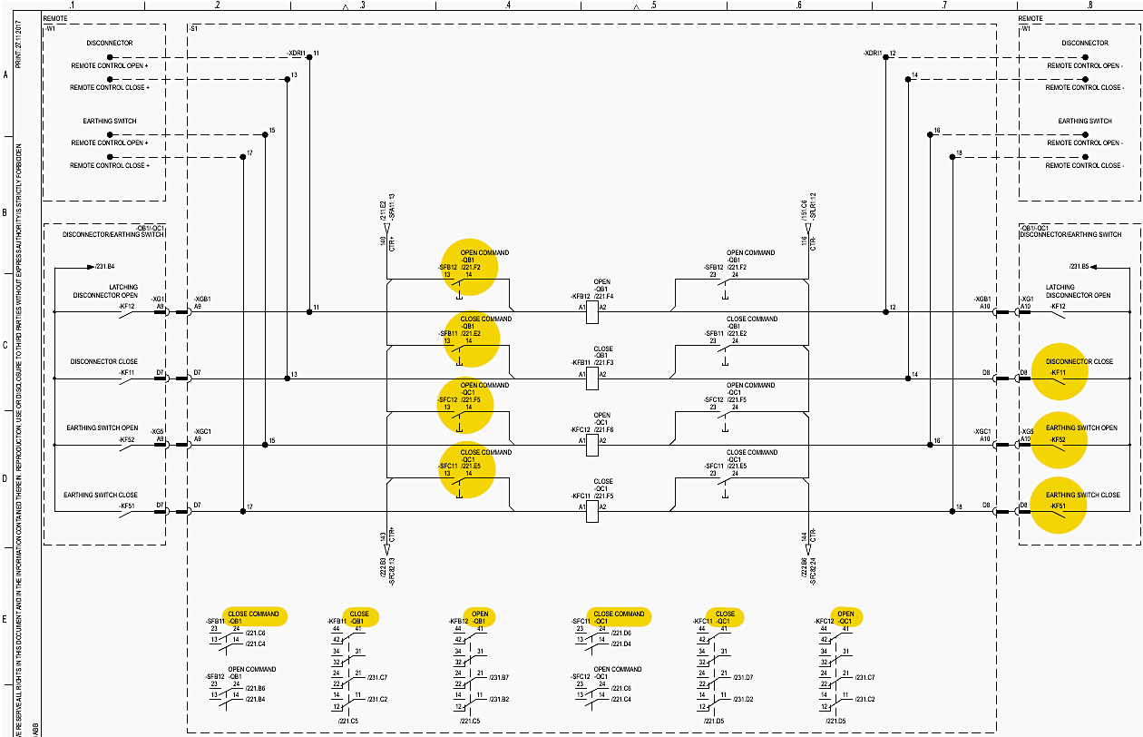
Unlike the instantaneous operation of the circuit breaker, disconnectors and earthing switches are motor-driven and take several seconds to operate. Their control logic is spread across Sheets 221 to 225.
-QB1 and -QC1 Operation: Sheet 221 shows the control for the primary disconnector -QB1 and earthing switch -QC1. Row B, Column 4 houses the “Close Command” and “Open Command” relays. For -QB1 to close, contactor -KF11 must be energized.
Fast Acting Earthing Switch (-QC8): Detailed on Sheet 222. Fast-acting switches are capable of closing onto a live busbar to safely ground a fault. The control is identical, using -KF81 (Close) and -KF82 (Open) at Row C, Column 5.
-QB9, -QC9, -QB11, -QC11, -QC12: Sheet 223 handles the -QB9/-QC9 pair. Sheet 224 controls the -QB11/-QC11 pair. Sheet 225 isolates the -QC12 earthing switch.
In all these sheets, strict electrical interlocks prevent an earthing switch from closing if its associated disconnector is closed, and vice versa.
Figure 11 – Disconnectors and Earthing Switches Control (Sheet 221)
9. Double Operation Interlocking
(Sheets 231–235)
To prevent severe electrical and mechanical failures, LCCs employ “Double Operation Interlocking.” This logic ensures that no two conflicting motor commands can be executed simultaneously within the same bay.
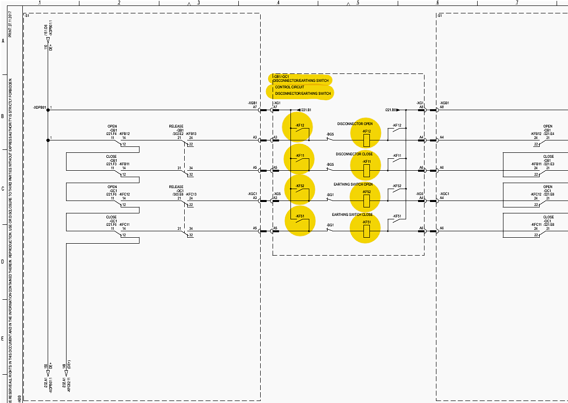
-QB1 / -QC1 Lockout: Sheet 231, Row B, Column 4 explicitly details this logic. The coil circuit for the -QB1 close contactor -KF11 is wired in series with the normally closed auxiliary contacts of the -QC1 contactors -KF51 and -KF52.
Systematic Implementation: This rigorous electrical lockout is systematically repeated for every opposing switch pair. Sheet 232 applies it to -QC8 (Row C, Col 4). Sheet 233 applies it to -QB9/-QC9 (Row B, Col 4).
Sheet 234 applies it to -QB11/-QC11 (Row B, Col 4). Sheet 235 applies it to -QC12 (Row C, Col 4).
Figure 12 – Double operation interlocking schematic (Sheet 231)
10. Interlocking Schemes
(Sheets 301–322)
While sheets 231-235 prevent simultaneous operation of local motors, the 300-series manages systemic, substation-wide interlocking logic to prevent switching errors that could cause massive short circuits.
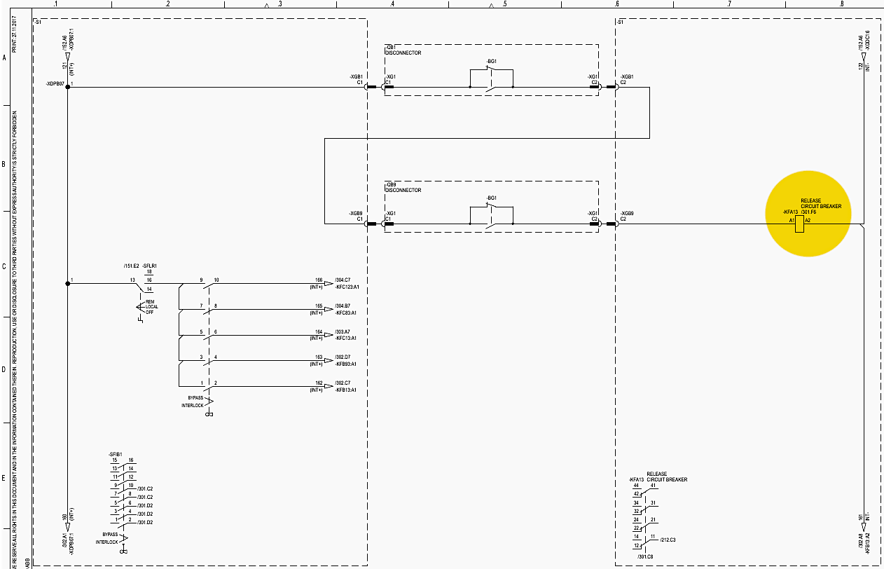
Circuit Breaker Interlocking (-QA1): Sheet 301 manages the logic that allows breaker -QA1 to be operated. The “Release Circuit Breaker” relay -KFA13 sits at Row C, Column 7.
Disconnector Interlocking (-QB1, -QB9, -QB11): Sheet 302 governs the disconnectors. Disconnectors cannot break load current; they can only be opened or closed when no current is flowing. The release relays (-KFB13 for -QB1, -KFB93 for -QB9) at Row D, Column 7 continuously monitor the status of the main circuit breaker -QA1.
If -QA1 is closed, the electrical release to move the disconnectors is denied, preventing an explosive electrical arc.
Figure 13 – Circuit Breaker Interlocking -QA1 (Sheet 301)
Earthing Switch Interlocking: Sheet 303 manages -QC1, -QC9, and -QC11. Earthing switch release relays (-KFC13, -KFC93) at Row D, Column 7 require absolute confirmation that all associated disconnectors are fully open and locked before allowing the earth to be applied.
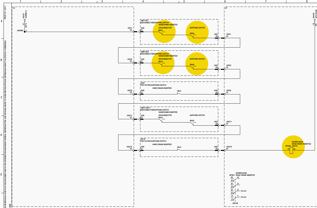
Hand Crank Lockout: Sheet 305 provides a final layer of interlocking.
If any limit switch detects a hand crank is inserted into ANY drive within the bay (-BG14 for -QB1, -BG54 for -QC1, etc., across Rows A to D), a bay-wide interlocking relay (-KFHK1, Row D, Col 7) drops out, paralyzing all remote and local electrical operations.
Station Interlocking: Sheets 321 and 322 route interlocking signals to and from external bays (e.g., Busbar Earthing Switches and adjacent feeders) via the -XDINT2 terminal blocks. This ensures that an earthing switch on the main busbar in a different cubicle will block operations in this specific -E1Q02 cubicle.
Figure 14 – Hand crank lockout schematic (Sheet 305)
11. Position Indication and Alarms
(Sheets 501–542)
The 500-series schematics are dedicated to human-machine interface elements: showing the operator the status of the plant and alerting them to failures.
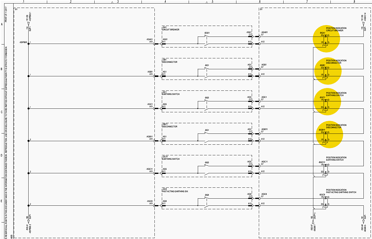
Position Indication (Local): Sheet 501 details how the mimic board LEDs are illuminated. At Row A, Column 7, the LED indicator `-BGA1` provides the position of the Circuit Breaker -QA1. Auxiliary contacts driven directly by the breaker’s physical mechanism (-XG01:C7, Row A, Col 6) switch the DC voltage between the red and green terminals of the LED.
Row B, Column 7 shows the identical setup for the -QB1 disconnector LED -BGB1. Row C covers the -QC1 earthing switch LED -BGC1.
Lamp Test: Sheet 502, Row C, Column 2 shows the “Lamp Test” push button -SFLT1. When pressed, it bypasses the auxiliary contacts and directly injects voltage to all mimic LEDs simultaneously to test for bulb failure.
Fault Indication (Alarms): Sheet 511 compiles the critical circuit breaker faults. Row B, Column 5 shows the “Close Block” alarm relay -KFAL01. Row C shows the “Trip 1 Block” relay -KFAL02. Sheet 512, Row B, Column 5 features the “MCB Tripped AC” alarm -KFAL06 and the “MCB Tripped DC” alarm -KFAL07.
SF6 Gas Monitoring Alarms: Sheet 514, Row B, Column 5 processes the signals from the gas density monitors. -KFAL10 indicates an SF6 Stage 1 (warning) on the -BP11 zone. -KFAL15 (Row D, Col 7) aggregates all Stage 2 (critical lockout) alarms into a “Collected Alarm” signal.
Alarm Annunciator: Sheet 533 shows the -PBAL1 multi-window alarm annunciator (Row B, Col 7). This device sits on the front of the panel and provides flashing lights and audible horns when any of the -KFAL fault relays trigger.
Figure 15 – How the mimic board LEDs are illuminated (Sheet 501)
12. Instrument Transformers: Measuring and Protection
(Sheets 701–741)
The high voltages and currents of the 132kV primary system must be stepped down to safe, measurable values (typically 1A and 100V) for the relays and meters.
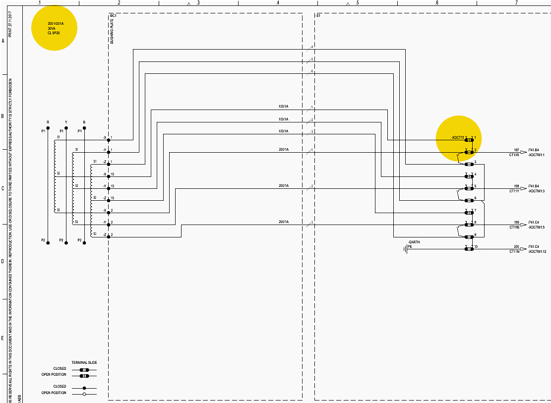
Current Transformer -BC1: Sheet 701 illustrates the wiring for the -BC1 current transformer. The secondary wires for the three phases (R, Y, B) emerge from the CT at Row B, Column 1 and route to the test disconnect terminal block -XDCT11 (Row C, Column 6).
Current Transformers -BC2 and -BC3: Sheet 702 routes the highly accurate -BC2 metering core to the -XDCT21 terminal block (Row C, Col 6). Sheet 703 shows the -BC2 protection core routing to -XDCT22. Sheets 704 and 705 route the -BC3 cores to -XDCT31 and -XDCT32 respectively.
All secondary star-points are rigorously tied to the -EARTH terminal (e.g., Sheet 701, Row D, Col 6) to establish a zero-voltage reference and ensure personnel safety.
Figure 16 – Current Transformer -BC1 schematic (Sheet 701)
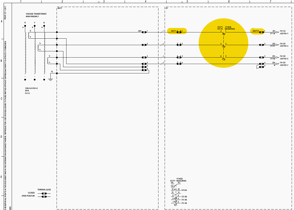
Voltage Transformer -BA11: The voltage transformer wiring is detailed on Sheets 721 through 723. Sheet 721 shows Main Winding 1 passing through the measuring MCB -FCVT1 (Row B, Col 3) before arriving at terminal -XDVT1 (Row B, Col 6). Sheet 722 routes Main Winding 2 through -FCVT2.
Sheet 723 routes the protection-class Main Winding 3 through -FCVT3.
Multimeter Connection: Sheet 741 shows how these CT and VT signals are utilized. The currents from -XDCT11 and voltages from -XDVT11 are routed directly into the -PGM1 digital multimeter (Row B, Col 6) mounted on the LCC front panel, allowing operators to monitor live power flow (Amps, Volts, MW, MVAR) directly from the bay.
Figure 17 – Voltage transformer -BA11 schematic (Sheet 721)
13. Spare Contacts Overview
(Sheets 801–809)
To allow for future expansion, external SCADA integration, or customer-specific logic, the switchgear provides a vast array of spare auxiliary contacts physically driven by the high-voltage devices.
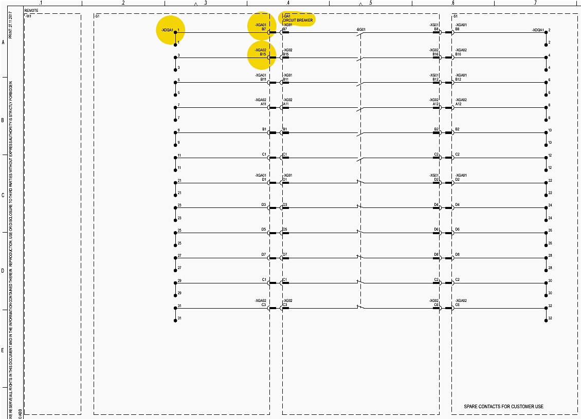
Circuit Breaker Spare Contacts: Sheet 801 maps the spare contacts from the -QA1 circuit breaker. Normally Open (NO) and Normally Closed (NC) contacts are brought from the heavy-duty -XGA01 and -XGA02 plugs to the easily accessible -XDQA1 terminal strip (Row B, Col 6).
Disconnector Spare Contacts: Sheet 802 handles the spares for the -QB1 disconnector, routed to -XDQB1. Sheet 804 routes -QB11 spares to -XDQB11. Sheet 807 routes -QB9 spares to -XDQB9.
Earthing Switch Spare Contacts: Sheet 803 routes spares for the -QC1 earthing switch to -XDQC1. Sheet 805 routes -QC11 spares to -XDQC11. Sheet 806 handles the fast-acting -QC8 spares at -XDQC8.
Sheet 808 covers -QC9, and Sheet 809 covers -QC12. This standardized routing ensures that any future modifications do not require opening the pressurized switchgear enclosures.
Figure 18 – Circuit breaker spare contacts schematic (Sheet 801)
14. Detailed Bill of Materials (BoM)
(Sheets 901–911)
The Bill of Materials (BOM) provides the precise manufacturer and part number for every physical component installed in the LCC, ensuring accurate procurement and replacement.
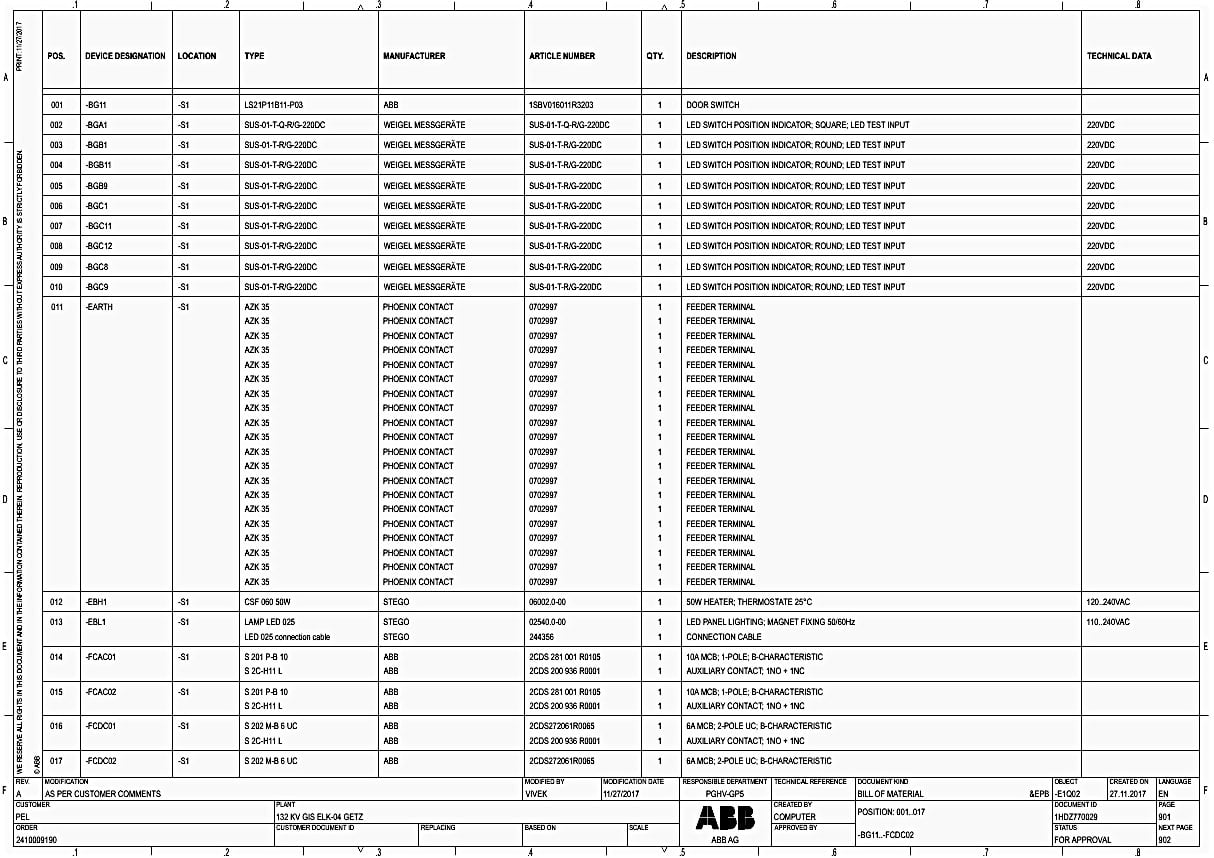
Door Switches and Mimic LEDs: Sheet 901 begins by listing -BG11 (Pos. 001) as an ABB Door Switch (Part: 1SBV016011R3203). Positions 002 through 010 detail the WEIGEL MESSGERÄTE LED indicators.
-BGA1 is a square LED for the breaker, while -BGB1 through -BGC9 are round LEDs for the disconnectors and earthing switches, all rated for 220VDC with built-in test inputs.
Heaters and MCBs: Position 012 specifies -EBH1, a STEGO 50W cubicle heater with an integrated thermostat (Part: 06002.0-00). Positions 014 to 025 itemize the ABB Miniature Circuit Breakers.
Relays: Starting at Position 026 on Sheet 902, the BOM lists the interface relays. -KFA13 is an ABB CR-M220DC4 relay (4-changeover contacts) with a mechanical flag and test button (Part: 1SVR405613R9000), mounted on an ABB CR-M4SS rail socket.
Positions 027 through 041 itemize the alarm relays (-KFAL01 to -KFAL15, which utilize gilded contacts (Part: 1SVR405618R9100) for superior reliability when switching low-current LED and SCADA signals.
Front Panel Controls: On Sheet 904, Position 068 outlines the -PBAL1 alarm annunciator, a UNITRO-FLEISCHMANN FSB1616. Position 071 is the -PGM1 ABB M2M basic digital multimeter.
Positions 072 through 089 list the specific Schlegel pushbuttons utilized on the control board (e.g., -SFA11, -SFB11), detailing the contact blocks (`BZII`), 3mm travel heads (`OKJT`), and colored lenses (`TOKJFGN` for green, `TOKJFRT` for red).
Terminal Blocks: Sheet 906, Position 096 begins the massive list of Phoenix Contact terminal blocks. The CT terminals (e.g., -XDCT11 utilize the `UTME 6` test disconnect terminal blocks (Part: 3047400) alongside specific sliding bridges (`SB-ME 2-8`) and test adapters (`PAI-4-FIX`) to safely short CTs during maintenance.
Heavy Connectors: Sheet 911 lists the 64-pole heavy-duty connectors. Positions 139 through 148 specify TE (TYCO) HD.64.Bu.C female inserts (Part: 2-1103033-3) for plugs -XGA01 through -XGC9.
Figure 19 – Detailed Bill of Materials (BoM) (Sheet 901)
15. Terminal and Cable Connection Plans
(Sheets 1001–1322)
The final section of the document serves as the physical wiring roadmap for the technicians assembling and commissioning the cubicle.
AC and Alarm Terminal Plans: Sheet 1001 illustrates the -XDAC0 incoming AC terminal strip. It maps exactly where the external 5-core cable connects to the internal wiring leading to -FCAC01 and the grounding bar.
Sheet 1002 maps -XDAC1, handling the distributed AC power to the external switch heaters. Sheet 1003 maps -XDAL1, detailing the exact pinouts for remote alarm signals.
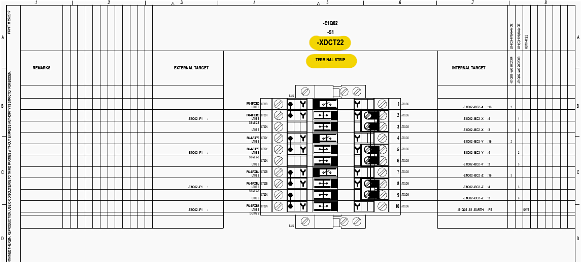
CT and VT Terminal Plans: Sheets 1004 through 1009 explicitly map the secondary wiring of every CT core onto the Phoenix Contact -XDCT strips. Sheet 1010 maps -XDCTM1, routing the selected currents into the front-panel multimeter.
Similarly, Sheets 1029 through 1036 provide pin-for-pin mapping of the voltage transformers -XDVT1, -XDVT2, `-XDVT3 and their routing to the multimeter -XDVTM1.
Figure 20 – Terminal connection plan for current transformer
DC Terminal Plans: Sheet 1011 handles the -XDDC0 DC infeed, and Sheet 1012 maps out -XDDC1, routing the protected DC positive and negative rails to various sub-circuits (Motors, Interlocking, Trips).
Remote and Protection Interfaces: To interface the LCC with the wider substation SCADA and protection relays, dedicated terminal strips are used. Sheet 1015 maps -XDPI1 (Protection Interface), which provides clean trip and close coil access points for external numerical relays.
Potential Busbars: To distribute common voltages (like a common DC negative or a common motor supply positive), the cabinet uses terminal strips bridged together, known as potential busbars. Sheets 1101 through 1109 detail -XDPB01 through -XDPB09.
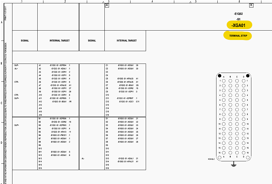
Heavy Plug Pinouts: Sheets 1201 through 1210 map the exact pinout of the 64-pole TE (TYCO) connectors. Sheet 1201 maps -XGA01 (Circuit Breaker), showing exactly which pin carries the close command, the trip command, and the auxiliary contact statuses down the umbilical cable to the physical switchgear drive.
Cable Table: The document concludes with the Cable Table (Sheets 1301-1322). This section provides a summarized list of every external cable required to hook up the LCC. For example, Sheet 1301 dictates that the Density Monitor cable -WG1001001 must be a `LIH(C)H-N (6×1,5) OZ` type, cut to a length of 10 meters, terminated with an M20 cable gland, and labeled with a `UC-WMTB (44X15)` cable marker.
This ensures field technicians cut and pull the exact correct umbilical cables for the heaters, motors, sensors, and instrument transformers.
Figure 21 – Terminal plan for circuit breaker (1st plug 64-pole)
16. Summary
The schematic package for the 132kV GIS LCC -E1Q02 represents a rigorously engineered control node that prioritizes failsafe operation, equipment protection, and operator safety.
By combining redundant DC trip paths, deep mechanical and electrical interlocking arrays, continuous trip circuit supervision, and clear visual mimic boards, the design guarantees that the heavy high-voltage switchgear can be operated, monitored, and maintained safely.
17. Attachment (PDF): Handbook of Power System Protection Maintenance and Field Operation
Download: Handbook of Power System Protection Maintenance and Field Operation (for premium members only):
Related electrical guides & articles





Edvard Csanyi
Hi, I'm an electrical engineer, programmer and founder of EEP - Electrical Engineering Portal. I worked twelve years at Schneider Electric in the position of technical support for low- and medium-voltage projects and the design of busbar trunking systems.I'm highly specialized in the design of LV/MV switchgear and low-voltage, high-power busbar trunking (<6300A) in substations, commercial buildings and industry facilities. I'm also a professional in AutoCAD programming.
Profile: Edvard Csanyi