


Estimated Study Time: 51 minutes
Metal-Clad Switchgear Schematics
This technical article provides a detailed analysis of the schematic drawings for a 13.8kV, 100MVA Transformer Feeder. The source material for this analysis is attached drawing document (PDF), detailing an ABB UNIGEAR-ZS1 metal-clad switchgear panel designated as =H.1.
 Schematics Analysis of 13.8kV 100MVA Transformer Feeder
The analysis starts with an overview of the Single Line Diagram (SLD) and physical panel specifications. From there, we will explain the mechanical and electrical operations of the vacuum circuit breaker, tracing the precise pathways of its charging motor, safety interlocks, and redundant trip coils.
The discussion will examine the distinct roles of the multi-core Current Transformers (CTs) and Voltage Transformers (VTs), explaining how they feed high-impedance differential schemes, precise metering instruments, and primary feeder protection relays.
To provide maximum practical value for field engineers and technical reviewers, we will conclude by identifying, analyzing, and resolving specific documentation inconsistencies hidden within the attached engineering drawings.
Here is the download link for the complete PDF document with drawings (256 pages). Open it up, so you can follow the discussion.
Schematics (PDF, 14.0 MB)
- An Overview of 13.8kV Metal-Clad Swichgear:
- The Vacuum Circuit Breaker +A-Q0:
- Current Transformer (CT) Arrangement:
- Voltage Transformer (VT) Arrangement and Distribution:
- Protection and Control: ABB REF 615:
- Tripping and Closing Circuits:
- Digital Metering and Local Indication
- Auxiliary Systems: Cooling, Heating & Earthing:
- Schematic Inconsistencies:
- Summary Notes
- Attachment (PDF) 🔗 Download ‘Low Voltage Design Handbook: From Principles to Application’
1. An Overview of 13.8kV Metal-Clad Swichgear
1.1 Switchgear Specifications and Ratings
The electrical parameters of the switchgear are established on the Rating Plate detailed on Sheet 1 (Row B, Column 4-7). The panel is engineered to operate at a nominal service voltage of 13.8kV, sitting within a maximum rated voltage envelope of 17.5kV.
The rated insulation level, expressed as Basic Insulation Level (BIL), is 17.5/38/95 kV, indicating the root-mean-square (RMS) withstand voltage and the peak lightning impulse withstand voltage, respectively. The system operates at a frequency of 60Hz.
The short-time withstand current (the fault current the busbars can physically and thermally endure without failure) is rated at 25kA for a duration of 3 seconds.
Furthermore, the peak withstand current, which accounts for the mechanical stresses generated by the asymmetrical peak of the first half-cycle of a fault, is rated at 65kA.
Figure 1 – Switchgear rating plate (Sheet 1)

1.2 The Single Line Diagram (SLD)
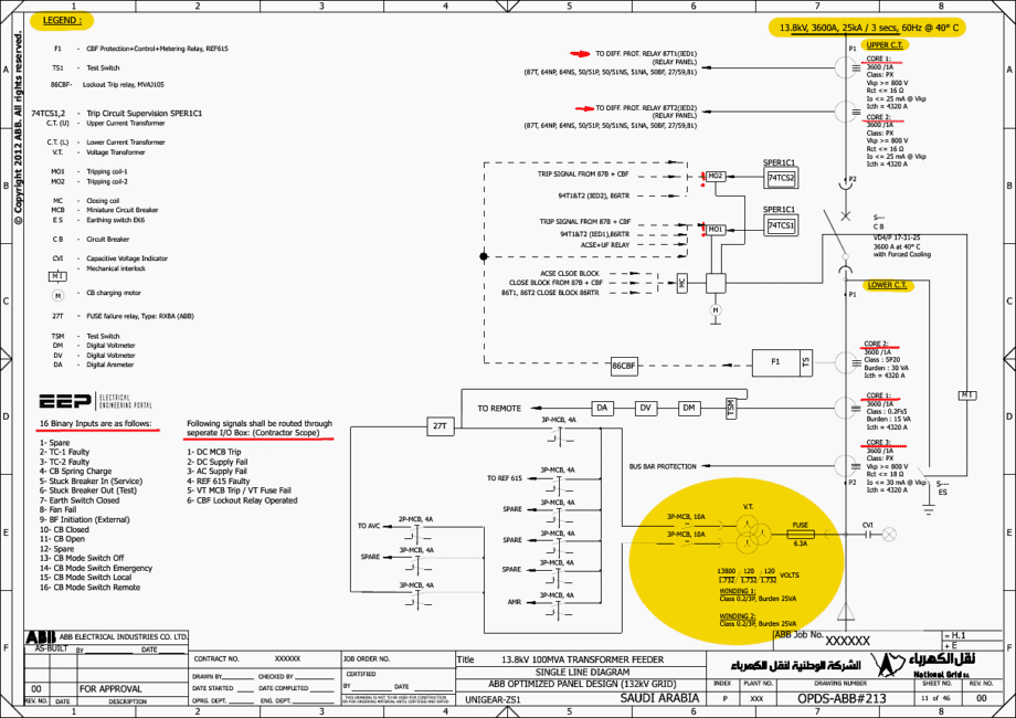
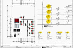
The Single Line Diagram, located on Sheet 11, serves as the feeder’s power flow and protection arrangement. Power decreases from the 3600A main busbar through various components we’ll mention now.
Immediately below the busbar connection, the Upper Current Transformers +B-CT are positioned. These CTs are dedicated exclusively to providing primary current data to the external transformer differential protection schemes.
Below the upper CTs sits the primary interrupting device, the Vacuum Circuit Breaker +A-Q0. This 3600A breaker is the critical actuator for all protection logic, designed to sever the circuit instantly upon receiving a trip command.
Further down the load side, the Voltage Transformers +C-VT are tapped off the main copper conductors. Protected by primary fuses, these VTs step the 13.8kV potential down to a safe 120V secondary voltage for metering and distance/voltage protection references.
Finally, at the very bottom of the SLD, the Earthing Switch +C-Q2 provides a mechanical means to ground the outgoing cable section, ensuring a zero-potential environment for maintenance personnel.
Figure 2 – Transformer feeder SLD

1.3 Physical Layout and Compartments
The switchgear physical layout is illustrated in the Cubicle Assembly drawing on Sheet 12. The ABB UNIGEAR-ZS1 is a highly compartmentalized, metal-clad design. Segregating the components into grounded metal compartments ensures that a failure (such as an internal arc fault) in one section does not propagate to destroy the entire switchgear.
As shown on the sectional side view (Sheet 12, Row C, Column 3), the switchgear is divided into four main zones. The Busbar Compartment is located at the top rear, housing the 2×120×100mm copper busbars.
Finally, the Low Voltage (LV) Compartment sits at the top front, securely isolated from the high voltage zones, housing the delicate protective relays, terminal blocks, and control wiring.
Figure 3 – Transformer feeder assembly

2. The Vacuum Circuit Breaker (+A-Q0)
The central switching mechanism responsible for energizing the feeder and clearing faults is the Vacuum Circuit Breaker, designated as +A-Q0. The detailed specifications for this critical component are located in the Apparatus List on Sheet 3 (Row A, Column 5).
2.1 Breaker Specifications
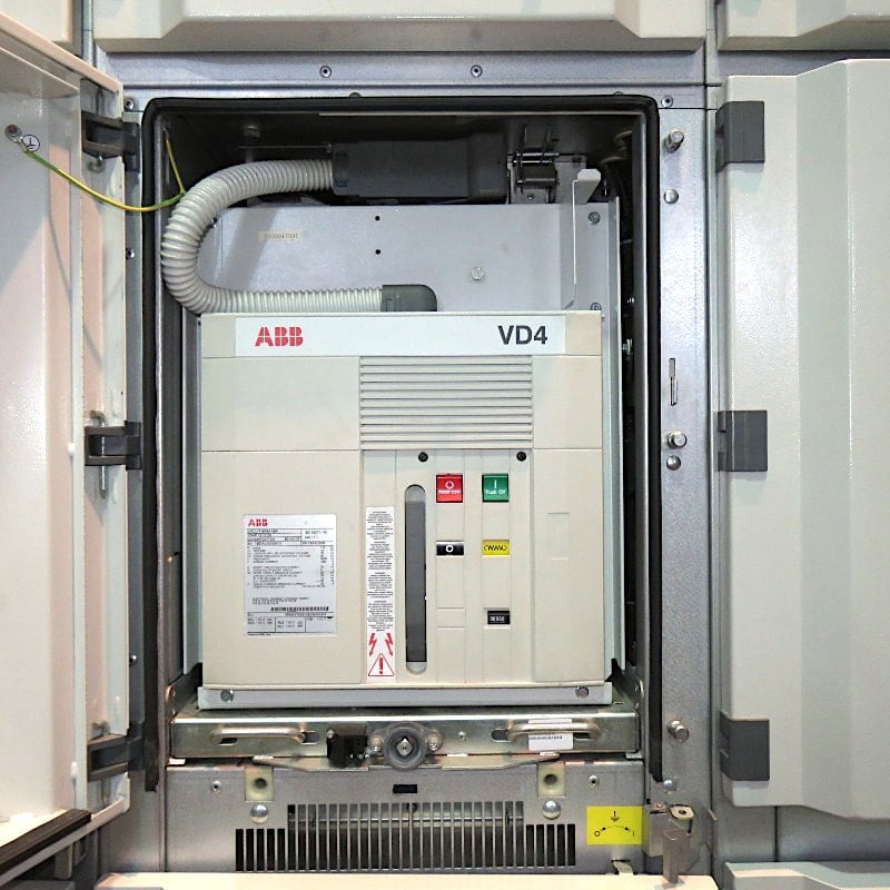
The device is specified as an ABB Vacuum Circuit Breaker, Type VD4/P17.32.25p275. It utilizes an embedded pole design, where the vacuum interrupter is encapsulated within epoxy resin. This encapsulation protects the fragile vacuum bottle from environmental contaminants, dust, moisture, and external mechanical impacts, ensuring long-term dielectric integrity.
The operating cycle defined by IEC standards for this breaker is O-0.3sec-CO-15Secs-CO. This notation dictates the breaker’s duty cycle during an autoreclosing sequence.
If the fault persists, it will wait 15 seconds before attempting one final Close-Open (CO) sequence. If the fault is still present, the breaker will lock out.
Figure 4 – Medium voltage draw-out vacuum circuit breaker, type VD4
2.2 Breaker Operating Mechanism and Control Coils
The mechanical operation of the VD4 breaker is driven by a strong spring mechanism. The energy required to close the breaker against the immense electromagnetic forces of a short circuit is stored in this spring. The charging of the spring is controlled by a 125 VDC charging motor -MS.
To ensure unparalleled reliability, the breaker features a suite of 125 VDC control coils, interconnected via a 58-Pole Plug -XB detailed on Sheet 46. These coils execute the commands from the protection relays and safety interlocks:
First Shunt Release OFF (-MO1) – This is the primary tripping coil. Energizing this coil releases the mechanical latch holding the breaker closed.
Second Shunt Release OFF (-MO2) – Complete redundancy is mandatory in protection engineering. -MO2 is an entirely separate coil acting on the same mechanical trip latch. If -MO1 burns out or its wiring fails, -MO2 ensures the breaker can still clear a catastrophic fault.
Shunt Release ON (-MC) – This is the closing coil. When energized, it unlatches the charged closing spring, slamming the vacuum contacts together.
Truck Blocking Coil (-RL2) – This electromechanical lock prevents the breaker truck from being physically racked into or out of the ‘Service’ position unless specific safety conditions are met (e.g., the breaker must be OPEN).
Closing Blocking Coil (-RL1) – This coil acts as a definitive veto over the closing circuit. If -RL1 is not energized (indicating a blocked state), the mechanical closing linkage is disabled, rendering the -MC coil ineffective even if it receives an electrical command.
This prevents the breaker from continuously “pumping” (opening and closing rapidly), which would destroy the vacuum bottles within seconds.
Figure 5 – Circuit breaker VD4 internal wiring

3. Current Transformer (CT) Arrangement
Current Transformers are the sensory organs of the switchgear, stepping down primary currents (up to 25,000A during a fault) to safe, standardized secondary levels (1 Ampere) that delicate microprocessor relays and meters can analyze.
The accuracy and saturation characteristics of these CTs dictate the entire success of the protection scheme. The schematics distinguish between Upper CTs +B-CT and Lower CTs +C-CT.
3.1 Upper CTs (+B-CT): High-Impedance Differential Protection
The Upper CTs +B-CT1, +B-CT2, and +B-CT3 are located in the busbar compartment and are dedicated to the external transformer differential protection schemes. They are defined in the Apparatus List on Sheet 3 (Rows B, C, D; Column 5).
These CTs contain two identical protection cores, both specified as 3600/1A, Class PX. The selection of Class PX is highly deliberate. Standard protection CTs (like Class 5P20) are defined by their composite error at a specific multiple of their rated current.
To eliminate this, Class PX CTs are strictly defined by their internal physical and magnetic characteristics.
3.1.1 Tracing the Upper CT Core 1 Wiring
The schematic routing for the Upper CT Core 1 is explicitly detailed on Sheet 15. This core is designated to feed the Transformer Differential Protection Relay 87T1 (IED1), which resides in a remote relay panel.
Following the wiring standard defined on Sheet 1 (PVC insulated H07VK – 2.5 mm2 Yellow color for CT circuits), the Red (R) phase current originates at terminal 1S1 of +B-CT1 (Sheet 15, Row B, Column 1). This wire is routed directly to pin 1 of the disconnecting terminal block -X21 (Sheet 15, Row B, Column 4).
Disconnecting terminal blocks are vital; they allow technicians to isolate the CT circuit or inject test currents without physically unscrewing wires from the CT itself.
Similarly, the Yellow (Y) phase originates at terminal 1S1 of +B-CT2 and routes to -X21 pin 3. The Blue (B) phase originates at 1S1 of +B-CT3 and routes to -X21 pin 5. To complete the circuit, the return path (Neutral) must be formed. This is achieved by physically bridging the 1S2 terminals of all three CTs together.
This common neutral wire is routed to -X21 pin 7.
On Sheet 15 (Row D, Column 4), the neutral path is solidly grounded at the local panel via the earth stud -EARTH1.
The wiring for Upper CT Core 2 is identical in topology, utilizing terminals 2S1 and 2S2, and is detailed on Sheet 16. It routes through terminal block -X22 to feed the redundant 87T2 differential relay (IED2).
Figure 6 -Upper CT Core 1 Wiring

3.2 Lower CTs (+C-CT): Metering and Feeder Protection
Positioned below the circuit breaker in the cable compartment, the Lower CTs +C-CT1, +C-CT2, and +C-CT3 monitor the current flowing directly to the load cables.
These are multi-core devices, engineered to serve three distinct functions simultaneously. The specifications are located on Sheet 4 (Rows A, B, C; Column 5).
3.2.1 Lower CT Core 1: Metering (Class 0.2Fs5)
Core 1 is a 3600/1A core dedicated to revenue and operational metering. It is classified as 0.2Fs5 with a 15 VA burden. The “0.2” indicates an extremely high accuracy class, guaranteeing a maximum measurement error of just 0.2% under normal operating conditions.
This precision is required for accurate power billing and SCADA monitoring.
The “Fs5” designation represents an Instrument Security Factor of 5. Metering instruments contain delicate electronics that would be instantly vaporized by the secondary currents generated during a 25kA primary short circuit. An Fs5 core is intentionally manufactured with a limited cross-sectional magnetic iron area.
The schematic routing for Core 1 begins on Sheet 17. Terminals 1S1 and 1S2 from all three phases are routed to the disconnecting block -X11. From there, the wiring transitions to Sheet 18, entering the test switch +D1-TSM. The test switch allows technicians to safely short-circuit the CT secondaries, because an open-circuited CT under load will generate dangerous kilovolt potentials.
After passing through the test switch, the current loops in series through the Digital Multifunction Meter +D-DM and the Digital Ammeter +D-DA.
Figure 7 – Lower CT Core 1: Metering (Class 0.2Fs5)

Figure 8 – Lower CT Core 1: Metering (Class 0.2Fs5) – continued

3.2.2 Lower CT Core 2: REF 615 Protection (Class 5P20)
Core 2 is a 3600/1A core designed for the primary overcurrent and earth fault protection of the feeder, supervised by the REF 615 relay. It is classified as 5P20 with a 30 VA burden. In stark contrast to the metering core, a protection core must absolutely never saturate during a fault.
If a protection CT saturates, the secondary waveform becomes clipped and distorted, causing the protective relay to calculate an artificially low fault current. This can lead to delays in tripping, resulting in equipment damage.
The wiring for Core 2 is shown on Sheet 19. Terminals 2S1 and 2S2 route to disconnecting block -X12 (Row B, Column 4). The phases pass through the REF 615 test switch +D1-TS1 at pins 1A/2A, 3A/4A, and 5A/6A. Exiting the test switch, they terminate directly at the heavy-duty analog current inputs of the REF 615 relay +D-F1.
The Red phase lands on pins X120:7/8, the Yellow phase on X120:9/10, and the Blue phase on X120:11/12 (Sheet 19, Row B, Column 6).
Figure 9 – Lower CT Core 2: REF 615 Protection (Class 5P20)

3.2.3 Lower CT Core 3: Busbar Differential Protection (Class PX)
Core 3 is a 3600/1A Class PX core, utilizing identical parameters to the Upper CTs (Vkp ≥ 800 V, Rct ≤ 18 Ω). This core forms the boundary for the main 13.8kV Busbar Differential Protection scheme (87B).
By summing the currents entering the busbar (from the transformer) and subtracting the currents leaving the busbar (via the feeders), the 87B relay can instantly detect a busbar short circuit. Traced on Sheet 20, terminals 3S1 and 3S2 map to terminal block -X13, then bridge across to the inter-panel feed-through block -X87 (Row A/B, Column 5) to connect with the central 87B relay panel.
The local neutral is established and grounded via -EARTH8.
Related electrical guides & articles






Edvard Csanyi
Hi, I'm an electrical engineer, programmer and founder of EEP - Electrical Engineering Portal. I worked twelve years at Schneider Electric in the position of technical support for low- and medium-voltage projects and the design of busbar trunking systems.I'm highly specialized in the design of LV/MV switchgear and low-voltage, high-power busbar trunking (<6300A) in substations, commercial buildings and industry facilities. I'm also a professional in AutoCAD programming.
Profile: Edvard Csanyi